Toyota Sienna Service Manual: Distance Control ECU Communication Stop Mode
DESCRIPTION
|
Detection Item |
Symptom |
Trouble Area |
| Distance Control ECU Communication Stop Mode |
|
|
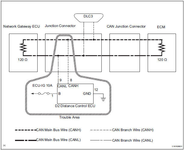
WIRING DIAGRAM
INSPECTION PROCEDURE
NOTICE:
- Turn the ignition switch off before measuring the resistances of CAN bus main wires and CAN bus branch wires.
- After the ignition switch is turned off, check that the key reminder warning system and light reminder warning system are not in operation.
- Before measuring the resistance, leave the vehicle as is for at least 1 minute and do not operate the ignition switch, any other switches, or the doors. If any doors need to be opened in order to check connectors, open the doors and leave them open.
HINT: Operating the ignition switch, any switches, or any doors triggers related ECU and sensor communication with the CAN. This communication will cause the resistance value to change.
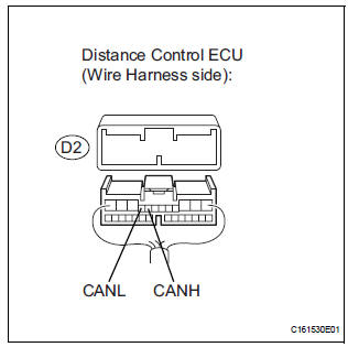
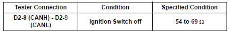
1 CHECK OPEN IN CAN BUS WIRE (DISTANCE CONTROL ECU)
- Turn the ignition switch off.
- Disconnect the distance control ECU connector.
- Measure the resistance according to the value(s) in the table below.
Standard resistance
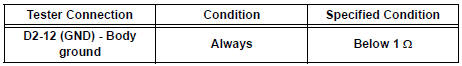
2 CHECK WIRE HARNESS (B, GND)
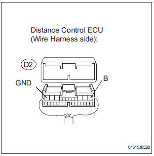
- Measure the resistance according to the value(s) in the table below.
Standard resistance
- Measure the voltage according to the value(s) in the table below.
Standard voltage
REPLACE DISTANCE CONTROL ECU ASSEMBLY
 Skid Control ECU Communication Stop Mode
DESCRIPTION
Detection Item
Symptom
Trouble Area
Skid Control ECU
Communication Stop
Mode
"ABS/VSC/TRC" is not displayed on the
" ...
 Gateway ECU Communication Stop Mode
DESCRIPTION
Detection Item
Symptom
Trouble Area
Gateway ECU
Communication Stop
Mode
"Gateway" is not displayed on the "Communication ...
Other materials:
Ignition Coil "A" Primary
HINT:
These DTCs indicate malfunctions relating to the primary circuit.
If DTC P0351 is set, check the No. 1 ignition coil with igniter circuit.
If DTC P0352 is set, check the No. 2 ignition coil with igniter circuit.
If DTC P0353 is set, check the No. 3 ignition coil with igniter circ ...
How to use this manual
GENERAL INFORMATION
1. GENERAL DESCRIPTION
(a) This manual is written in accordance with SAE J2008.
(b) Repair operations can be separated mainly in the following 3 processes:
(1) Diagnosis
(2) Removing / Install ...
Throttle Actuator Control Motor Current Range
/ Performance
DTC P2118 Throttle Actuator Control Motor Current Range
/ Performance
DESCRIPTION
The ETCS (Electronic Throttle Control System) has a dedicated power supply
circuit. The voltage (+BM)
is monitored and when it is low (less than 4 V), the ECM determines that there
is a malfunction in the
ETCS ...
