Toyota Sienna Service Manual: Door Courtesy Switch Circuit
DESCRIPTION
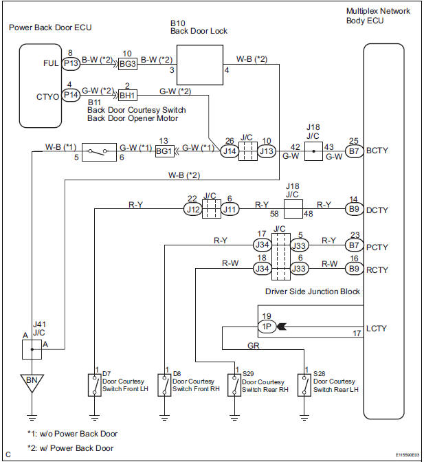
The Multiplex network body ECU detects the condition of the door courtesy switch assembly.
WIRING DIAGRAM
INSPECTION PROCEDURE
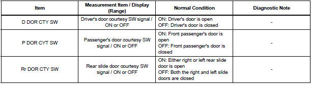
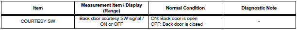
1 READ VALUE OF INTELLIGENT TESTER
- Connect the intelligent tester to DLC3.
- Turn the ignition switch to ON and push the intelligent tester main switch ON.
- Select the items below in the DATA LIST, and read the displays on the intelligent tester
BODY NO.1:
BACK DOOR:
2 INSPECT COURTESY LIGHT SWITCH
- Inspect each of the courtesy light switch continuity
3 INSPECT BACK DOOR LOCK ASSEMBLY
- Inspect the courtesy light switch terminal of the back door lock assembly
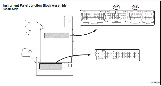
4 CHECK HARNESS AND CONNECTOR
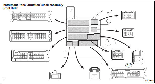
- Disconnect the 1P, B7 and B9 connector from the instrument panel junction block assembly
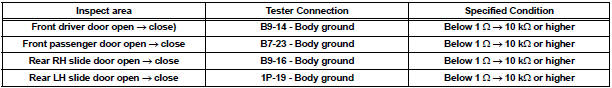
- Check the resistance between each of the terminals of instrument panel junction block assembly connector side and body ground as shown in the chart below.
Resistance
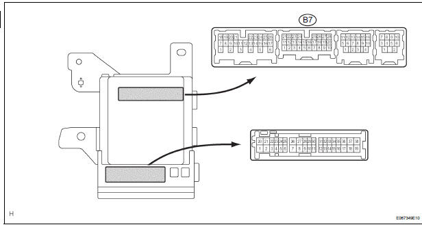
5 INSPECT INSTRUMENT PANEL JUNCTION BLOCK ASSEMBLY (BACK DOOR COURTESY LIGHT SWITCH CIRCUIT)
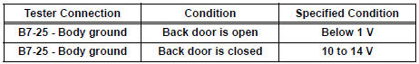
- Measure voltage between the terminal B7-25 of the multiplex network body ECU and body ground.
Voltage
6 CONFIRM VEHICLE TYPE
- Check the vehicle models.
A: w/o Power back door
B: w/ Power back door
7 INSPECT POWER BACK DOOR SYSTEM
- Inspect the power back door circuit
REPAIR OR REPLACE HARNESS OR CONNECTOR
 Automatic Light Control Sensor Circuit
DESCRIPTION
The Multiplex network body ECU receives the signal from the automatic light
control sensor.
HINT:
DTC code is output when malfunction of automatic light control sensor or open or
...
 Door LOCK Position Circuit
DESCRIPTION
This circuit detects the state of the door lock detection sensor and send it
to the Multiplex network body
ECU.
WIRING DIAGRAM
INSPECTION PROCEDURE
1 READ VALUE OF INTELLIGENT T ...
Other materials:
Safety information for Safety Connect
Important! Read this information before using Safety Connect.
Exposure to radio frequency signals
The Safety Connect system installed in your vehicle is a low-power
radio transmitter and receiver. It receives and also sends out radio
frequency (RF) signals.
In August 1996, the Federal Communi ...
GPS Antenna Error/ GPS Antenna Power Source Error
DTC 58-40 GPS Antenna Error
DTC 58-41 GPS Antenna Power Source Error
DTC 80-40 GPS Antenna Error
DTC 80-41 GPS Antenna Power Source Error
DESCRIPTION
DTC No.
DTC Detection Condition
Trouble Area
58-40
GPS antenna error
Wire harness
GPS ...
Diagnosis system
1. DESCRIPTION
When troubleshooting OBD II (On-Board
Diagnostics) vehicles, an intelligent tester
(complying with SAE J1987) must be connected to
the DLC3 (Data Link Connector 3) of the vehicle.
Various data in the vehicle's ECM (Engine Control
Module) can be then read.
& ...
