Toyota Sienna 2010-2026 Owners Manual: Driving in vehicle-to-vehicle distance control mode
This mode employs a radar sensor to detect the presence of vehicles up to approximately 400 ft. (120 m) ahead, determines the current vehicle-to-vehicle following distance, and operates to maintain a suitable following distance from the vehicle ahead.
Note that vehicle-to-vehicle distance will close in when traveling on long downhill slopes.
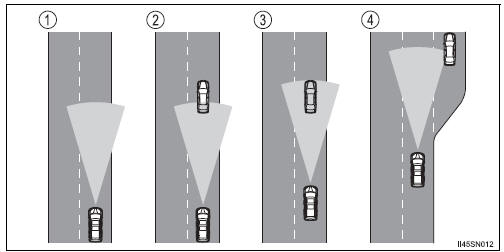
- Example of constant speed cruising When there are no vehicles ahead
The vehicle travels at the speed set by the driver. The desired vehicle-tovehicle distance can also be set by operating the vehicle-to-vehicle distance control.
- Example of deceleration cruising When the vehicle ahead is driving slower than the set speed
When a vehicle is detected running ahead of you, the system automatically decelerates your vehicle. When a greater reduction in vehicle speed is necessary, the system applies the brakes. A warning tone warns you when the system cannot decelerate sufficiently to prevent your vehicle from closing in on the vehicle ahead.
- Example of follow-up cruising When following a vehicle driving slower than the set speed
The system continues follow-up cruising while adjusting for changes in the speed of the vehicle ahead in order to maintain the vehicle-to-vehicle distance set by the driver.
- Example of acceleration When there are no longer any vehicles ahead driving slower than the set speed
The system accelerates until the set speed is reached. The system then returns to constant speed cruising.
 Canceling and resuming the speed control
Pulling the lever toward you
cancels the cruise control.
The speed setting is also canceled
when the brakes are applied.
Pushing the lever up resumes
the cruise control and returns
...
 Approach warning
When your vehicle is too close to a vehicle ahead, and sufficient automatic
deceleration via the cruise control is not possible, the display
will flash and the buzzer will sound to alert the driver. ...
Other materials:
ECM / PCM Processor
DTC P0606 ECM / PCM Processor
DESCRIPTION
The ECM continuously monitors its internal processors (CPUs), A/F sensor
transistors and heated oxygen
sensor (HO2S) transistors. This self-check ensures that the ECM is functioning
properly. These are
diagnosed by internal "mirroring" of t ...
Vvt sensor
COMPONENTS
ON-VEHICLE INSPECTION
1. CHECK VVT SENSOR OUTPUT VOLTAGE
(a) Turn the ignition switch to the ON position.
(b) Check the voltage between the specified terminal
and body ground.
Standard voltage
(c) While turning the crankshaft pulley by hand,
measure the voltage betwe ...
How to proceed with
troubleshooting
HINT:
*: Use the intelligent tester.
1 VEHICLE BROUGHT TO WORKSHOP
2 CUSTOMER PROBLEM ANALYSIS
(a) Confirm problem symptoms
3 CHECK MULTIPLEX COMMUNICATION SYSTEM*
Check if the multiplex communication system DTC is output.
HINT:
The center airbag sensor assembly of this system ...
