Toyota Sienna Service Manual: Dtc check / clear
1. DTC CHECK/CLEAR (WHEN USING SST CHECK WIRE):
(a) DTC check
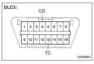
(1) Using SST, connect terminals TC and CG of the DLC3.
SST 09843-18040
(2) Turn the ignition switch to the ON position.
(3) Read the DTCs from the ABS warning light on the combination meter.
HINT:
If no code appears, inspect the TC and CG
terminal circuit and the ABS warning light circuit.
(4) As an example, refer to the chart below for the blinking patterns of the normal system code and trouble codes 11 and 21.
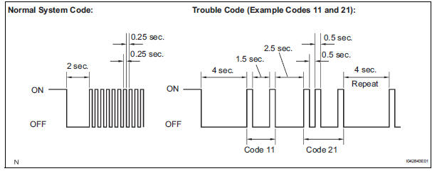
(5) The codes are explained in the code table (See page BC-14).
(6) After completing the check, disconnect terminals TC and CG of the DLC3, and turn off the display.
If 2 or more DTCs are detected at the same time, the DTCs will be displayed in ascending order.
(b) DTC clear
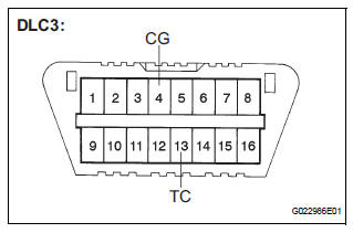
(1) Using SST, connect terminals TC and CG of the DLC3.
SST 09843-18040 (2) Turn the ignition switch to the ON position.
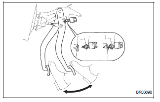
3) Clear the DTCs stored in the ECU by depressing the brake pedal 8 times or more within 5 seconds.
(4) Check that the warning light indicates the normal system code.
(5) Remove the SST from the terminals of the DLC3.
HINT: Clearing the DTCs cannot be performed by removing the battery cable.
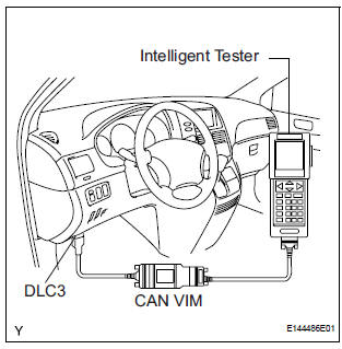
2. DTC CHECK/CLEAR (WHEN USING INTELLIGENT TESTER):
(a) DTC check
(1) Connect the intelligent tester to the DLC3.
(2) Turn the ignition switch to the ON position.
(3) Read the DTCs by following the prompts on the tester screen.
(b) DTC clear
(1) Connect the intelligent tester to the DLC3.
(2) Turn the ignition switch to the ON position.
(3) Operate the intelligent tester to clear the codes.
HINT: Refer to the intelligent tester operator's manual for further details.
3. END OF DTC CHECK/CLEAR
(a) Turn the ignition switch to the ON position.
(b) Check that the ABS warning light goes off within approximately 3 seconds.
 Diagnosis system
1. DESCRIPTION
(a) Release the parking brake pedal.
(b) Check the warning lights.
When ignition switch is turned ON, check that the
ABS warning light and brake warning light come on
for 3 ...
 Freeze frame data
1. FREEZE FRAME DATA
(a) Whenever a DTC is detected or the ABS operates,
the skid control ECU stores the current vehicle
(sensor) state as freeze frame data.
The skid control ECU stores the numb ...
Other materials:
Auto Up Operation does not Fully Close Power Window (Jam
Protection Function is Activated)
DESCRIPTION
If AUTO UP operation does not fully close the power window, the following
conditions may be the cause.
The reset of the power window motor has not been completed,
resulting in activation of the jam
protection function.
The memory of the power window switch misse ...
Installation
1. INSTALL AMPLIFIER ANTENNA ASSEMBLY
Engage the 16 clamps to install the amplifier
antenna assembly.
Install the 3 bolts.
Connect the connectors.
2. INSTALL ROOF HEADLINING ASSEMBLY
3. INSTALL ANTENNA ASSEMBLY WITH HOLDER
Install the antenna assembly ...
On-vehicle inspection
1. INSPECT REAR AIRBAG SENSOR (VEHICLE NOT
INVOLVED IN COLLISION)
Perform a diagnostic system check.
2. INSPECT REAR AIRBAG SENSOR (VEHICLE
INVOLVED IN COLLISION AND AIRBAG HAS NOT
DEPLOYED)
Perform a diagnostic system check.
When the quarter panel of the vehicle or ...
