Toyota Sienna Service Manual: DTC check / clear
HINT: If the system cannot enter the diagnostic mode, inspect all AVC-LAN communication signals and repair or replace problem parts.
1. STARTING DIAGNOSTIC MODE
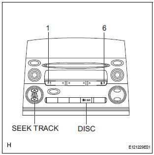
- Turn the ignition switch to the ACC position.
- Turn off the audio system.
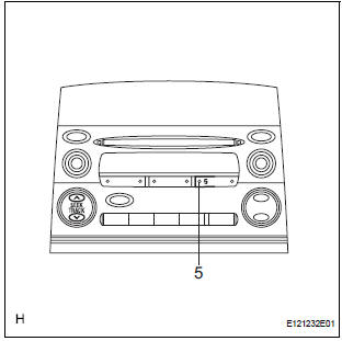
- While pressing the preset switches "1" and "6" at the same time, press the "DISC" switch 3 times.
HINT: A beep is emitted 3 times and the diagnostic function is activated. The system enters the all element illumination mode and the switch check mode.
2. ALL ELEMENT ILLUMINATION MODE AND SWITCH CHECK MODE
HINT: Illumination status of all switches and operations of the panel switches can be checked.
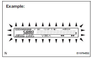
- Check that all elements are on.
- When pressing each panel switch, check that a beep is emitted.
NOTICE: Pressing the "SEEK TRACK UP" switch transfers the screen to the stereo jack adapter connection check screen. Check the operation of this switch by confirming the transfer of the screen.
3. STEREO JACK ADAPTER CONNECTION CHECK MODE
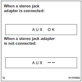
- Press the "SEEK TRACK UP" switch.
- Check if the stereo jack adapter is recognized.
HINT: Vehicles that do not have a stereo jack adapter also have this function.
NOTICE: This function is not to check connection information on an external device, but to check recognition information on a stereo jack adapter.
4. SERVICE CHECK MODE
- Press the "SEEK TRACK UP" switch.
HINT: For details of the service check mode, refer to "6.
CHECK DTC" and "7. DTC CLEAR/RECHECK".
5. FINISHING DIAGNOSTIC MODE
- Press the "DISC" switch for 2 seconds or more, or turn the ignition switch of
6. CHECK DTC
HINT: Illustrations may differ from the actual vehicle depending on the device settings and options. Therefore, some detailed areas may not be shown exactly the same as on the actual vehicle.
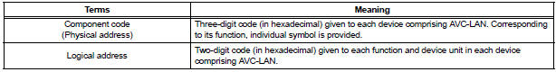
- Reference: In the system check mode, the system check and the diagnostic memory check are performed, and the check results are displayed in ascending order of the component codes (physical address).
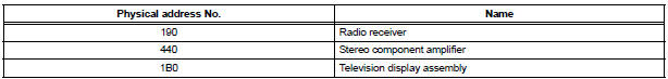
- Service check result display
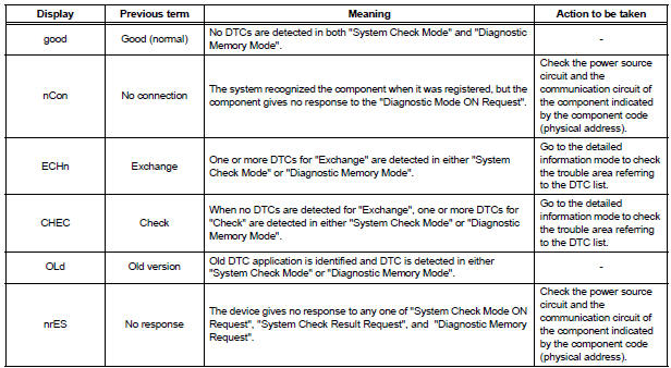
- Device name and physical address
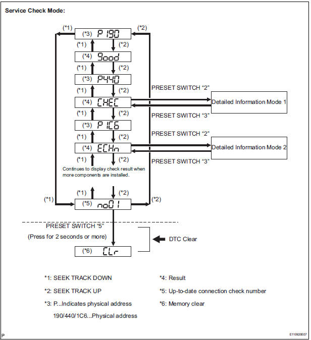
- Service check mode
- Press the "SEEK TRACK" switch to see the check result of each component.
- The component code (physical address) is displayed first, and then the check result follows.
HINT:
- If all check results are "good", the system judges that no DTC exists
- If the preset switch "1" is pressed in the service check mode, service check is performed again.
- This illustration is only an example and may differ in cases such as for each option part and output DTCs
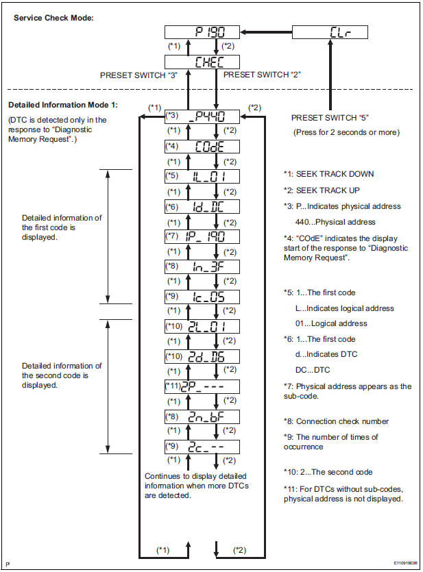
- Detailed information mode 1
HINT:
- "Detailed information mode 1" is displayed when there is no response to "System Check Result Request" and DTC is detected only in "Diagnostic Memory Request".
- The component device code (physical address) is displayed first, and then the check result follows.
- This illustration is only an example and may differ in cases such as for each option part and output DTCs.
- Press the preset switch "2" to go to the "Detailed Information Mode 1".
- Press the "SEEK TRACK" switch to display the physical address and DTC of the component.
- Press the preset switch "3" to go to the "Service Check Mode".
- Distinguish between the displays of the responses to "System Check Result Request" and "Diagnostic Memory Request". In order to distinguish the information detected in "System Check Mode" and "Diagnostic Memory Mode" in "ECHn", "CHEC", and "OLd" in "Detailed Information Mode 1", refer to the following:
- "SyS" is displayed before the detailed codes detected as a result of "System Check Result Request" are displayed.
- "COdE" is displayed before the detailed codes detected as a result of "Diagnostic Memory Request" are displayed.
HINT:
- The response to "System Check Result Request" is the current information given from each ECU as a result of the system check.
- The response to "Diagnostic Memory Request" contains the information received from each ECU or stored in each ECU in the past.
- The response to "Diagnostic Memory Request" is the output DTCs as a result of the diagnostic memory check or the DTCs received from each ECU.
- "System Check Result Request (SyS)" is displayed first, and then the logical address and DTC appear in order.
- "Diagnostic Memory Request (COdE)" is displayed first, and then the logical address, DTC, sub-code, connection check number, and the number of occurrence appear in order.
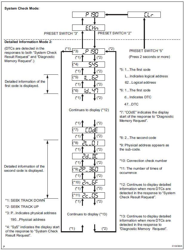
- Detailed information mode 2
HINT:
- "Detailed information mode 2" is displayed when DTCs are detected in the responses to both "System Check Result Request" and "Diagnostic Memory Request".
- The component device code (physical address) is displayed first, and then the check result follows.
- This illustration is only an example and may differ in cases such as for each option part and output DTCs.
- Press the preset switch "2" to go to the "Detailed Information Mode 2".
- Press the "SEEK TRACK" switch to display the physical address and DTC of the component.
- Press the preset switch "3" to go to the "Service Check Mode".
- Distinguish between the displays of the responses to "System Check Result Request" and "Diagnostic Memory Request". In order to distinguish the information detected in "System Check Mode" and "Diagnostic Memory Mode" in "ECHn", "CHEC", and "OLd" in "Detailed Information Mode 2", refer to the following:
- "SyS" is displayed before the detailed codes detected as a result of "System Check Result Request" are displayed.
- "COdE" is displayed before the detailed codes detected as a result of "Diagnostic Memory Request" are displayed.
HINT:
- The response to "System Check Result Request" is the current information given from each ECU as a result of the system check.
- The response to "Diagnostic Memory Request" contains the information received from each ECU or stored in each ECU in the past.
- The response to "Diagnostic Memory Request" is the output DTCs as a result of the diagnostic memory check or the DTCs received from each ECU.
- "System Check Result Request (SyS)" is displayed first, and then the logical address and DTC appear in order.
- "Diagnostic Memory Request (COdE)" is displayed first, and then the logical address, DTC, sub-code, connection check number, and the number of occurrence appear in order.
7. DTC CLEAR/RECHECK
- Clearing All DTC Memory (when clearing all the memory of the DTCs previously detected).
- When the preset switch "5" is pressed for 2 seconds or more during "Service Check Mode", the DTCs for all components are cleared. ("CLr" is displayed at this time.)
HINT:
- A beep sound is emitted once when the DTC memory is completely cleared.
- When the DTC memory for all the components is cleared, only the component codes (physical address) are displayed.
- After the DTC memory is cleared, the "Service Check Mode" is restored.
- Clearing Individual DTC Memory (when clearing the memory of the DTC previously detected individually).
- When the preset switch "5" is pressed for 2 seconds or more during "Detailed Information Mode 1" or "Detailed Information Mode 2", the DTCs for the target component are cleared.
HINT:
- A beep sound is emitted once when the DTC memory is completely cleared.
- When the DTC memory is cleared, only the component code (physical address) is displayed for the target component.
- After the DTC memory is cleared, the "Service Check Mode" is restored.
- To check DTCs, press the preset switch "1" and perform the system check again.
- Press the preset switch "1" to perform the service check again, and check that no DTCs are displayed for all the component codes (physical address).
 Terminals of ECU
1. RADIO RECEIVER (10 SPEAKER SYSTEM)
*1: with Rear Seat Entertainment System
2. RADIO RECEIVER (6 SPEAKER SYSTEM)
*1: with Rear Seat Entertainment System
*2: without Rear Seat ...
 Diagnostic trouble code chart
COMMUNICATION DIAGNOSIS:
DVD PLAYER:
CD PLAYER
IN-DASH CD CHANGER
...
Other materials:
Transmission Range Sensor Circuit Malfunction
(PRNDL Input)
DESCRIPTION
The park/neutral position switch detects the shift lever position and sends
signals to the ECM.
MONITOR DESCRIPTION
These DTCs indicate a problem with the park/neutral position switch and the
wire harness in the park/
neutral position switch circuit.
The park/neutral po ...
Reassembly
1. INSTALL REAR SEAT STAY SUB-ASSEMBLY
Install the seat stay sub-assembly with the nut.
Torque: 5.5 N*m (56 kgf*cm, 49 in.*lbf)
2. INSTALL NO. 2 SEAT CUSHION SPRING ASSEMBLY
RH
3. INSTALL LOCUS CABLE RH
Install the locus cable RH with the nut.
Torque: 5.5 N*m (56 kgf*cm, ...
Repair
1. STEERING OFF CENTER REPAIR PROCEDURE
(a) Inspect steering wheel off center.
(1) Apply masking tape to the top center of the
steering wheel and steering column upper
cover.
(2) Drive the vehicle in a straight line for 100
meters at a constant speed of 35 mph (56 km/
h), and hold the ...
