Toyota Sienna Service Manual: ECM Power Source Circuit
DESCRIPTION
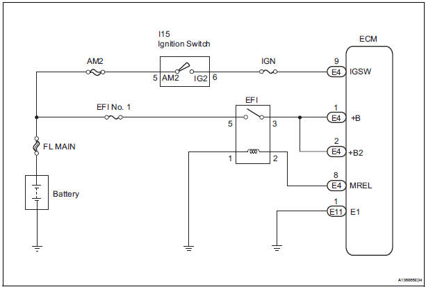
When the ignition switch is turned to the ON position, the battery voltage is applied to terminal IGSW of the ECM. The ECM MREL output signal causes a current to flow to the coil, closing the contacts of the EFI relay and supplying power to terminal +B of the ECM.
If the ignition switch is turned off, the ECM holds the EFI relay ON for a maximum of 2 seconds to allow for the initial setting of the throttle valve.
WIRING DIAGRAM
INSPECTION PROCEDURE
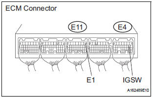
1 INSPECT ECM (+B VOLTAGE)
- Turn the ignition switch to the ON position.
- Measure the voltage according to the value(s) in the table below.
Standard voltage
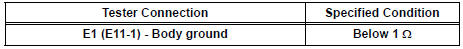
2 CHECK HARNESS AND CONNECTOR (ECM - BODY GROUND)
- Disconnect the E11 ECM connector.
- Measure the resistance according to the value(s) in the table below.
Standard resistance: Check for open
- Reconnect the ECM connector.
3 INSPECT ECM (IGSW VOLTAGE)
- Turn the ignition switch to the ON position.
- Measure the voltage according to the value(s) in the table below.
Standard voltage
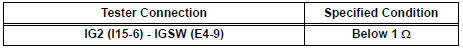
4 CHECK FUSE (IGN FUSE)
- Remove the IGN fuse from the driver side junction block.
- Measure the IGN fuse resistance.
Standard resistance: Below 1 Ω
- Reinstall the IGN fuse.
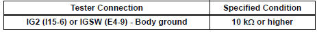
5 CHECK HARNESS AND CONNECTOR (IGNITION SWITCH - ECM)
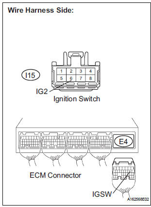
- Disconnect the E4 ECM connector.
- Disconnect the I15 ignition switch connector.
- Measure the resistance according to the value(s) in the table below.
Standard resistance: Check for open
Check for short
- Reconnect the ECM connector.
- Reconnect the ignition switch connector.
6 INSPECT IGNITION SWITCH ASSEMBLY
- Inspect the ignition or starter switch assembly
7 CHECK FUSE (AM2 FUSE)
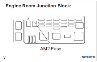
- Remove the AM2 fuse from the engine room junction block.
- Measure the resistance according to the value(s) in the
table below.
Standard resistance: Below 1 Ω
- Reinstall the AM2 fuse
REPAIR OR REPLACE HARNESS OR CONNECTOR (IGNITION SWITCH - BATTERY)
8 INSPECT ECM (MREL VOLTAGE)
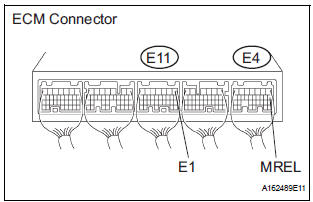
- Turn the ignition switch to the ON position.
- Measure the voltage according to the value(s) in the table below.
Standard voltage
9 CHECK FUSE (EFI NO.1 FUSE)
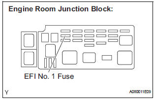
- Remove the EFI No. 1 fuse from the engine room junction block.
- Measure the EFI No. 1 fuse resistance.
Standard resistance: Below 1 Ω
- Reinstall the EFI No. 1 fuse.
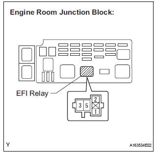
10 INSPECT RELAY (EFI RELAY)
- Remove the EFI relay from the engine room junction block.
- Measure the EFI relay resistance.
Standard resistance
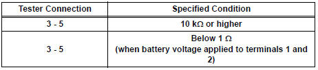
- Reinstall the EFI relay.
11 CHECK HARNESS AND CONNECTOR (EFI RELAY - ECM)
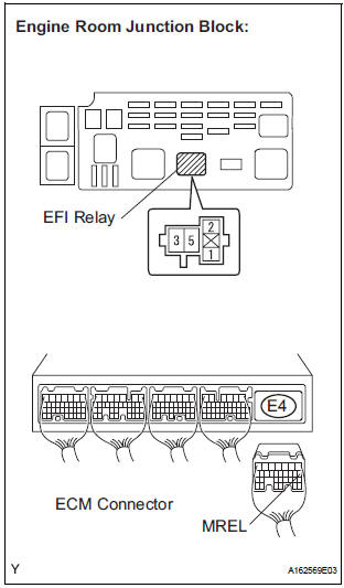
- Check the harness and connector between the EFI relay and ECM.
- Remove the EFI relay from the engine room junction block.
- Disconnect the E4 ECM connector.
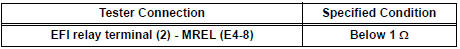
- Measure the resistance according to the value(s) in the table below.
Standard resistance: Check for open
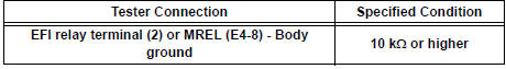
Check for short
12 CHECK HARNESS AND CONNECTOR (EFI RELAY - ECM)
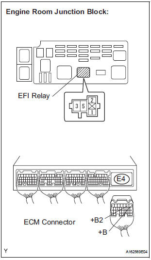
- Remove the EFI relay from the engine room junction block.
- Disconnect the E4 ECM connector.
- Measure the resistance according to the value(s) in the table below.
Standard resistance: Check for open
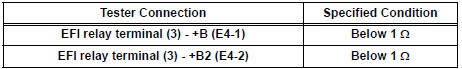
Check for short
- Reinstall the EFI relay.
- Reconnect the ECM connector.
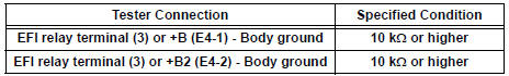
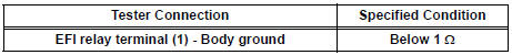
13 CHECK HARNESS AND CONNECTOR (EFI RELAY - BODY GROUND)
- Check the harness and connector between the EFI relay and body ground.
- Measure the resistance according to the value(s) in the table below.
Standard resistance : Check for open
- Reinstall the EFI relay.
- Reconnect the ECM connector.
REPAIR OR REPLACE HARNESS OR CONNECTOR (EFI RELAY - BATTERY)
 EVAP System
RELATED DTCS
If any EVAP system DTCs are set, the malfunctioning area can be determined
using the table below.
NOTICE:
If the 0.02 inch reference pressure difference between the first and ...
 VC Output Circuit
DESCRIPTION
The ECM constantly uses 5 V from the battery voltages supplied to the +B (BATT)
terminal to operate the
microprocessor. The ECM also provides this power to the sensors through the VC
...
Other materials:
Standard bolt
HOW TO DETERMINE BOLT STRENGTH
SPECIFIED TORQUE FOR STANDARD BOLTS
HOW TO DETERMINE NUT STRENGTH
HINT:
*: Nut with 1 or more marks on one side surface of the nut.
Use a nut with the same nut strength classification number
(or greater) as the bolt strength classification number ...
SRS airbags
The SRS airbags inflate when the vehicle is subjected to certain
types of severe impacts that may cause significant injury to the
occupants. They work together with the seat belts to help reduce
the risk of death or serious injury.
SRS front airbags
SRS driver airbag/front passenger ...
Air conditioning controls
Adjusting the temperature setting
Press “” on the “TEMP” button to
increase the temperature and “”
to decrease the temperature.
Adjusting the fan speed
Press “” on
to increase the fan speed and “”
to decrease
the fan speed.
Press the “OFF” button to turn the ...
