Toyota Sienna Service Manual: ECU Power Source Circuit
DESCRIPTION
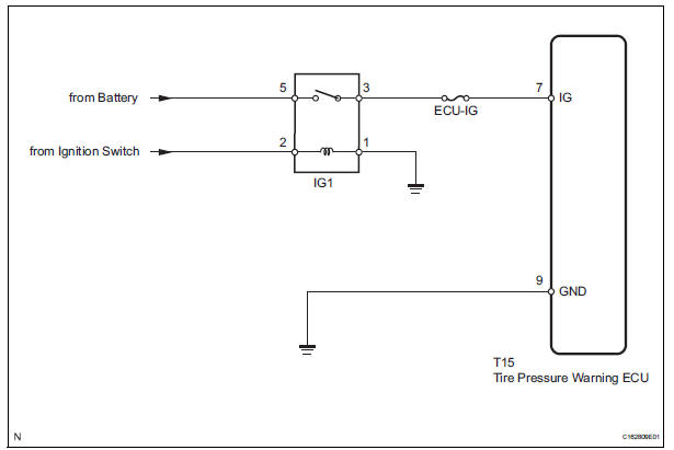
This is the power source for the tire pressure warning ECU.
WIRING DIAGRAM
INSPECTION PROCEDURE
NOTICE: When replacing the tire pressure warning ECU, read the transmitter IDs stored in the old ECU using the intelligent tester and write them down before removal.
It is necessary to register an ID code after replacing the tire pressure warning valve and transmitter and/or the tire pressure warning ECU (See page TW-20).
1 INSPECT FUSE (ECU-IG)
(a) Remove the ECU-IG fuse from the instrument panel junction block.
(b) Measure the resistance of the fuse.
Standard resistance: Below 1 Ω

2 INSPECT IGNITION RELAY NO. 1
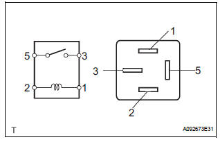
(a) Remove the IG1 relay from the instrument panel junction block.
(b) Measure the resistance according to the value(s) in the table below.
Standard resistance 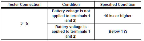

3 CHECK HARNESS AND CONNECTOR (ECU - BATTERY AND BODY GROUND)
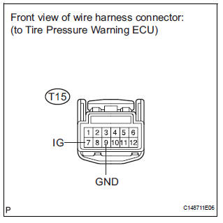
(a) Disconnect the T15 ECU connector.
(b) Measure the voltage according to the value(s) in the table below.
Standard voltage 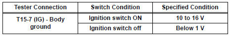
(c) Measure the resistance according to the value(s) in the table below.
Standard resistance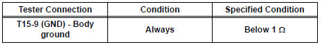

PROCEED TO NEXT CIRCUIT INSPECTION SHOWN IN PROBLEM SYMPTOMS TABLE (See page TW-28)
 Tire Pressure Warning Light Circuit
DESCRIPTION
If the ECU detects trouble, the tire pressure warning light blinks (comes on
after blinking for 1 minute) and
tire pressure monitor is cancelled at the same time. At this time, the ECU ...
 TC and CG Terminal Circuit
DESCRIPTION
DTC output mode is set by connecting terminals 13 (TC) and 4 (CG) of the
DLC3. The DTCs are indicated
by blinks of the tire pressure warning light.
WIRING DIAGRAM
HINT:
When eac ...
Other materials:
Skid Control ECU Communication Stop Mode
DESCRIPTION
Detection Item
Symptom
Trouble Area
Skid Control ECU
Communication Stop
Mode
"ABS/VSC/TRC" is not displayed on the
"Communication Bus Check" screen of the
intelligent tester
Applies to "Skid Control ...
Rear Blower Motor Circuit
DESCRIPTION
Power to the rear blower motor is supplied from the battery via the RR A/C
relay.
The rear blower motor speed level varies between 0 and 31 based on the voltage
difference measured
between the terminals of the motor.
The voltage difference measured between the terminals of th ...
Removal
1. REMOVE INSTRUMENT CLUSTER NO.1 FINISH PANEL CENTER
2. REMOVE INSTRUMENT CLUSTER NO.2 FINISH
PANEL CENTER
3. REMOVE INSTRUMENT CLUSTER FINISH PANEL GARNISH
4. REMOVE NAVIGATION RECEIVER ASSEMBLY WITH BRACKET
Remove the 4 screws.
Disconnect the connector and remove the
n ...
