Toyota Sienna Service Manual: ECU Power Source Circuit
DESCRIPTION
This circuit provides power to operate the theft deterrent (warning) ECU.
WIRING DIAGRAM
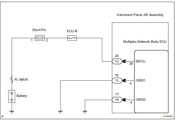
INSPECTION PROCEDURE
1 INSPECT FUSE (ECU-B)
- Remove the ECU-B fuse from the engine room J/B.
- Measure the resistance.
Standard resistance: Below 1 Ω
2 CHECK INSTRUMENT PANEL J/B ASSEMBLY (POWER SOURCE)
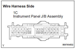
- Disconnect the 1C J/B connector.
- Measure the voltage according to the value(s) in the table below.
Standard voltage
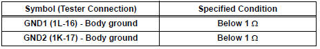
3 CHECK HARNESS AND CONNECTOR (INSTRUMENT PANEL J/B ASSEMBLY - BODY GROUND)
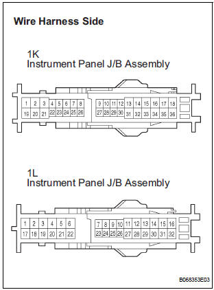
- Disconnect the 1K and 1L J/B connector.
- Measure the resistance according to the value(s) in the table below.
Standard resistance
REPLACE INSTRUMENT PANEL J/B ASSEMBLY
 Security Indicator Light Circuit
DESCRIPTION
Even when the theft deterrent system is in the disarmed state, the security
indicator blinks due to a signal
output from the immobiliser system. The security indicator blinks continuou ...
 Engine hood courtesy
switch
Engine hood courtesy
switch
Inspection
1. INSPECT ENGINE HOOD COURTESY SWITCH
Measure the resistance according to the value(s) in
the table below.
Standard resistance
If the result is not as specified, r ...
Other materials:
Open in Rear Curtain Shield Squib LH Circuit
DTC B1636/88 Open in Rear Curtain Shield Squib LH Circuit
DESCRIPTION
The rear curtain shield squib LH circuit consists of the center airbag sensor
assembly and the curtain
shield airbag assembly LH.
The circuit instructs the SRS to deploy when deployment conditions are met.
DTC B1636/88 ...
Summary of the Blind Spot Monitor
The Blind Spot Monitor is a system that has 2 functions:
The Blind Spot Monitor function
Assists the driver in making the decision when changing lanes
The Rear Cross Traffic Alert function
Assists the driver when backing up
These functions use same sensors.
BSM main switch
Pre ...
Removal
1. REMOVE REAR WHEEL
2. REMOVE SKID CONTROL SENSOR WIRE (for 2WD)
(a) Disconnect the skid control sensor connector.
(b) Remove the bolt and disconnect the bracket from
the rear axle beam assembly.
HINT:
Separate the RH side by the same procedures as
the LH side.
3. SEPARATE SPEED SENSO ...
