Toyota Sienna Service Manual: ECU Power Source Circuit
DESCRIPTION
The position control ECU and switch assembly (power seat control switch and ECU) is contained in the switch assembly.
During manual operation, only one switch signal is accepted. If signals are input from 2 or more switches simultaneously, all of them are ignored, except when signals are input from the front vertical switch and lifter switch simultaneously. In this case, the signal from the lifter will operate.
During automatic operation, a manual switch input will override any other operations, i.e. automatic operations will stop and the manual input operation only will be accepted. For example, if a manual switch input is activated during a seat store/restore operation, the previous operation will cease and manual operation will be performed. After the manual operation is performed, the previous automatic operation will not resume.
The power mirror store/restore operation is unaffected by manual switch inputs.
The front power seat switch does not allow the restore operation of the power seat when the system detects that the voltage of terminal SYSB is less than 8.0 +- 0.5 V for 30 msec. or is more than 10 +- 0.5 V for 30 msec.
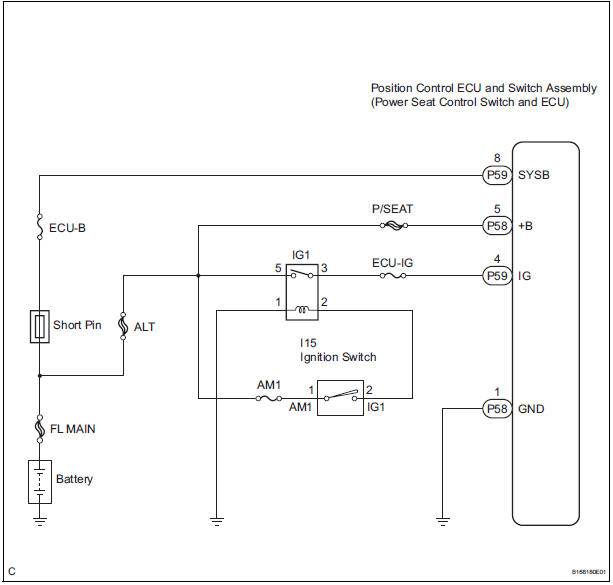
This circuit is the power source circuit for the position control ECU and switch assembly (power seat control switch and ECU).
HINT:
- Manual adjustment of the slide and reclining can be performed even when the front power seat switch is not functional if current is allowed to flow into terminals +B and SYSB.
- The lumber support function can always be used because its circuit does not include the ECU and differs from other functions (reclining, slide, lifter, and front vertical functions.)
WIRING DIAGRAM
INSPECTION PROCEDURE
1 INSPECT POSITION CONTROL ECU AND SWITCH ASSEMBLY (POWER SEAT CONTROL SWITCH AND ECU POWER SOURCE CIRCUIT)
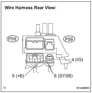
- Disconnect the position control ECU and switch assembly connectors.
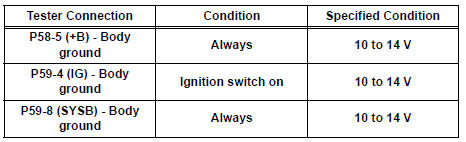
- Measure the voltage according to the value(s) in the table below.
Standard voltage
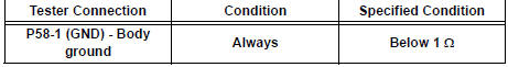
2 INSPECT POSITION CONTROL ECU AND SWITCH ASSEMBLY (POWER SEAT CONTROL SWITCH AND ECU GROUND CIRCUIT)
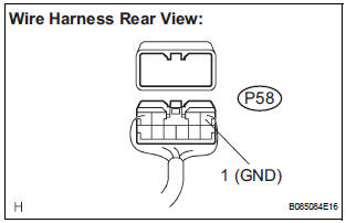
- Measure the resistance according to the value(s) in the table below.
Standard resistance
PROCEED TO NEXT CIRCUIT INSPECTION SHOWN IN PROBLEM SYMPTOMS TABLE
 Driving Position Memory Switch Circuit (w/ Memory)
DESCRIPTION
The seat memory switch sends signals to the outer mirror control ECU LH via
the multiplex
communication system to memorize a given seat position. This memory system does
not use a po ...
 Seat heater system
PARTS LOCATION
...
Other materials:
Diagnosis system
1. CHECK DLC3
The vehicle's ECU uses ISO 15765-4 for
communication protocol. The terminal arrangement
of the DLC3 complies with SAE J1962 and matches
the ISO 15765-4 format.
NOTICE:
*: Before measuring the resistance, leave the
vehicle as is for at least 1 minute and do not
ope ...
Installation
1. INSTALL REAR DOOR GLASS WEATHERSTRIP
Install the rear door glass weatherstrip.
2. INSTALL SLIDE DOOR WINDOW ASSEMBLY
3. INSTALL REAR DOOR GLASS RUN
4. INSTALL REAR DOOR TRIM BOARD SUBASSEMBLY
5. INSTALL SIDE TRIM BOARD COVER REAR
6. INSTALL REAR DOOR WINDOW FRAME SUBASSEMBLY
7. INSTA ...
Terminals of ECU
1. CENTER AIRBAG SENSOR ASSEMBLY (w/ Side
Airbag)
2. CENTER AIRBAG SENSOR ASSEMBLY (w/o Side
Airbag)
...
