Toyota Sienna Service Manual: Engine coolant temperature sensor
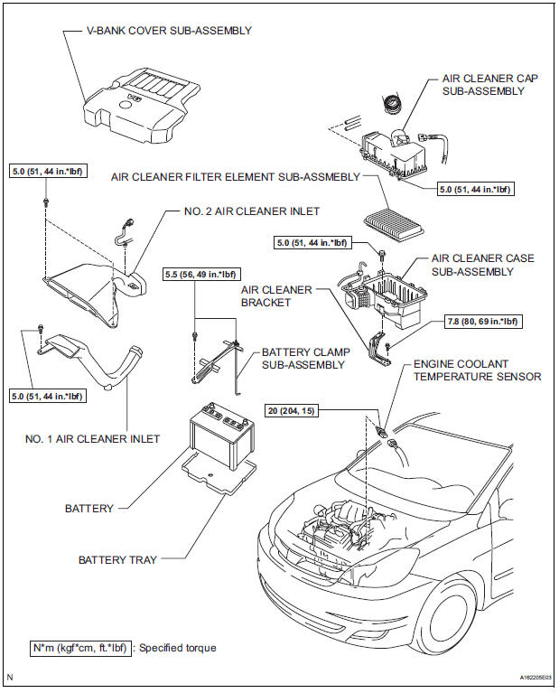
COMPONENTS
REMOVAL
1. DRAIN ENGINE COOLANT (See page CO-6) 2. REMOVE V-BANK COVER SUB-ASSEMBLY (See page EM-28) 3. REMOVE NO. 2 AIR CLEANER INLET (See page EM- 28) 4. REMOVE NO. 1 AIR CLEANER INLET (See page EM- 28) 5. REMOVE AIR CLEANER CAP SUB-ASSEMBLY (See page ES-493) 6. REMOVE AIR CLEANER CASE SUB-ASSEMBLY (See page EM-28) 7. REMOVE ENGINE COOLANT TEMPERATURE SENSOR
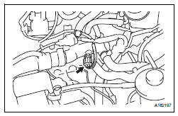
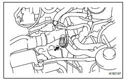
(a) Remove the engine coolant temperature sensor connector.
(b) Remove the engine coolant temperature sensor.
INSPECTION
1. INSPECT ENGINE COOLANT TEMPERATURE SENSOR
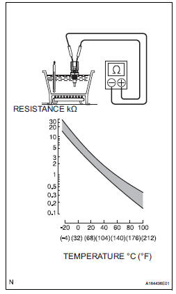
(a) Using an ohmmeter, measure the resistance between the terminals.
Standard resistance 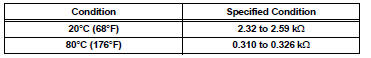
- If the result is as specified, do not replace the engine coolant temperature sensor
- If the result is not as specified, replace the engine coolant temperature sensor.
| NOTICE: In case of checking the engine coolant temperature sensor in water, do not allow water to go into the terminals. After checking, dry the engine coolant temperature sensor. |
INSTALLATION
1. INSTALL ENGINE COOLANT TEMPERATURE SENSOR
(a) Install the engine coolant temperature sensor.
Torque: 20 N*m (204 kgf*cm, 15 ft.*lbf) (b) Connect the engine coolant temperature sensor connector.
2. INSTALL AIR CLEANER CASE SUB-ASSEMBLY (See page EM-59) 3. INSTALL AIR CLEANER CAP SUB-ASSEMBLY (See page ES-496) 4. INSTALL NO. 1 AIR CLEANER INLET (See page EM- 59) 5. INSTALL NO. 2 AIR CLEANER INLET (See page EM- 60) 6. ADD ENGINE COOLANT (See page CO-7) 7. INSPECT FOR ENGINE COOLANT LEAK (See page CO-1) 8. INSTALL V-BANK COVER SUB-ASSEMBLY (See page EM-63)
 Crankshaft position sensor
Components
Removal
1. Remove compressor and magnetic clutch
HINT:
(See page AC-227 )
2. REMOVE CRANKSHAFT POSITION SENSOR
(a) Disconnect the crankshaft position sensor
connector.
(b) R ...
 Knock sensor
COMPONENTS
REMOVAL
1. DISCHARGE FUEL SYSTEM PRESSURE
(See page FU-13)
2. REMOVE V-BANK COVER SUB-ASSEMBLY (See
page EM-28)
3. DRAIN ENGINE COOLANT (See page CO-6)
4. REMOVE WINDSHIE ...
Other materials:
Display Signal Circuit between Video Terminal and Television Display
DESCRIPTION
This is the display signal circuit from the video terminal to the television
display assembly.
WIRING DIAGRAM
INSPECTION PROCEDURE
1 CHECK HARNESS AND CONNECTOR (TELEVISION DISPLAY ASSEMBLY - VIDEO
TERMINAL)
Disconnect the connectors from the video terminal and
tele ...
Automatic door locking and unlocking systems
The following functions can be set or cancelled: For instructions on
customizing, refer to
Function
Operation
Shift position linked door
locking function
Shifting the shift lever out of P locks all the
doors
Shift position linked door
unlocking function
...
Adjustment
CAUTION:
Do not stare at the luminous portion of the laser
during adjustment. The intensity of the laser light is
low, but it may result in loss of sight.
If operation is not carried out as specified, there may
be a risk that you are exposed to hazardous radiation.
HINT:
...
