Toyota Sienna Service Manual: Engine front oil seal
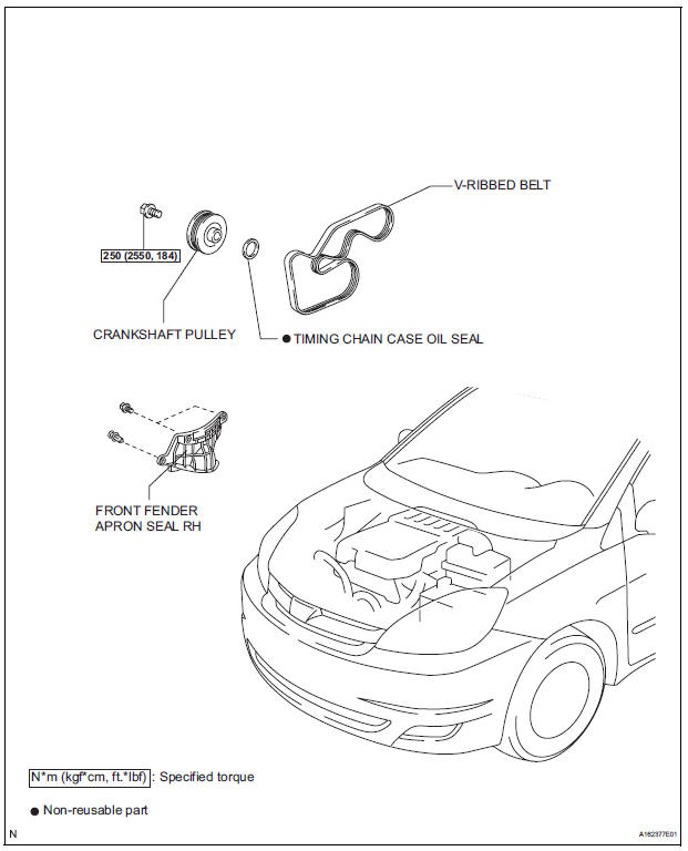
COMPONENTS
REMOVAL
1. REMOVE FRONT WHEEL RH 2. REMOVE FRONT FENDER APRON SEAL RH (See page EM-26) 3. REMOVE V-RIBBED BELT (See page EM-6) 4. REMOVE CRANKSHAFT PULLEY
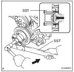
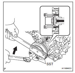
(a) Using SST, loosen the crankshaft pulley bolt.
SST 09213-70011 (09213-70020), 09330-00021
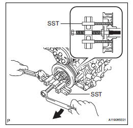
(b) Using SST, remove the crankshaft pulley bolt and crankshaft pulley.
SST 09950-50013 (09951-05010, 09952-05010, 09953-05020, 09954-05021)
5. REMOVE TIMING CHAIN CASE OIL SEAL
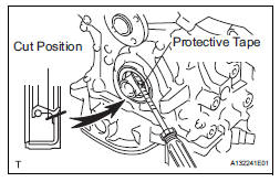
(a) Using a screwdriver, pry out the oil seal.
HINT:
Tape the screwdriver tip before use.
| NOTICE: After the removal, check the crankshaft for damage. If it is damaged, smooth the surface with 400-grit sandpaper. |
INSTALLATION
1. INSTALL TIMING CHAIN CASE OIL SEAL
(a) Apply MP grease to a new oil seal lip.
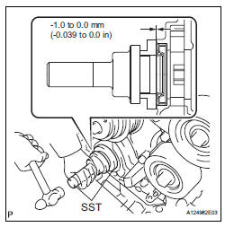
(b) Using SST and a hammer, tap in the oil seal until its surface is flush with the timing chain cover edge.
SST 09223-22010, 09506-35010
NOTICE:
|
2. INSTALL CRANKSHAFT PULLEY
(a) Align the pulley set key with the key groove of the pulley, and slide on the pulley.
(b) Using SST, install the pulley bolt.
SST 09213-70011 (09213-70020), 09330-00021 Torque: 250 N*m (2550 kgf*cm, 184 ft.*lbf)
3. INSTALL V-RIBBED BELT (See page EM-7) 4. INSTALL FRONT FENDER APRON SEAL RH (See page EM-62) 5. INSTALL FRONT WHEEL RH Torque: 103 N*m (1050 kgf*cm, 76 ft.*lbf)
 Drive belt
COMPONENTS
REMOVAL
1. REMOVE FRONT WHEEL RH
2. REMOVE FRONT FENDER APRON SEAL RH (See
page EM-26)
3. REMOVE V-RIBBED BELT
(a) Using SST, release the belt tension by turning the
belt tensi ...
 Engine rear oil seal
Components
Removal
1. REMOVE AUTOMATIC TRANSAXLE ASSEMBLY (for
2WD)
HINT:
See page AX-163.
2. REMOVE AUTOMATIC TRANSAXLE ASSEMBLY (for
4WD)
HINT:
See page AX-167.
3. REMOVE DRIVE PLATE A ...
Other materials:
Power Slide Door Pulse Sensor Malfunction on
Rear Left Door
DTC B2224 Power Slide Door Pulse Sensor Malfunction on
Rear Left Door
DESCRIPTION
A pulse sensor is built into slide door LH for jam and foreign
object detection and for slide door position
detection. The jam and foreign object detection feature of the pulse sensor
monitors the o ...
On-vehicle inspection
1. INSPECT THROTTLE BODY
(a) Listen to the throttle control motor operating sounds.
(1) Turn the ignition switch to the ON position.
(2) When pressing the accelerator pedal position
sensor lever, listen to the running motor. Make
sure that no friction noise comes from the
motor.
If fricti ...
Sound Signal Circuit between Radio and Navigation Assembly and
Television Display Assembly
DESCRIPTION
The television display assembly sends an RSE sound signal to the radio and
navigation assembly through
this circuit. The sound signal that has been sent is amplified by the stereo
component amplifier, and then
is sent to the speakers.
If there is an open or short in the circuit ...
