Toyota Sienna Service Manual: Engine Immobiliser System Malfunction
DTC B2799 Engine Immobiliser System Malfunction
DESCRIPTION
This DTC is output when the ECM detects errors in communication between the transponder key ECU and the ECM, or in the communication lines. This DTC is also output when an engine start is attempted while the ECU communication ID between the transponder key ECU and the ECM are different. Before troubleshooting for this DTC, make sure that there is no DTC detected in the transponder key ECU. If there is key code-related DTC detected in the transponder key ECU, repair it first.
|
DTC No. |
DTC Detection Condition |
Trouble Area |
|
B2799 |
|
|
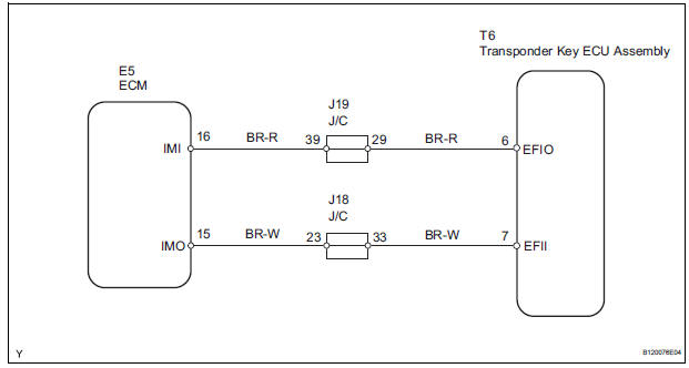
WIRING DIAGRAM
INSPECTION PROCEDURE
1 CHECK HARNESS AND CONNECTOR (TRANSPONDER KEY ECU ASSEMBLY - ECM)
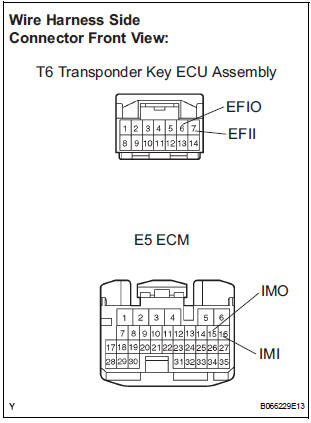
- Disconnect the T6 ECU and E5 ECM connectors.
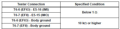
- Check the resistance of the wire harness side connectors.
Resistance
2 CHECK TRANSPONDER KEY ECU ASSEMBLY
- After replacing the transponder key ECU assembly with a normally functioning transponder key ECU assembly, check that the engine starts.
OK: The engine starts
END
 No Communication in Immobiliser System
DTC B2796 No Communication in Immobiliser System
DTC B2798 Communication Malfunction No. 2
DESCRIPTION
These codes are stored in the memory when a key that does not have a
transponder chip is ins ...
 Cruise control
...
Other materials:
Sound Signal Circuit between Radio Receiver and Stereo Jack Adapter
DESCRIPTION
The stereo jack adapter sends an external device sound signal to the radio
receiver through this circuit.
The sound signal that has been sent is amplified by the stereo component
amplifier or radio receiver, and
then is sent to the speakers.
If there is an open or short in th ...
Opening and closing
Front moon roof
Vehicles without a rear moon
roof
Vehicles with a rear moon roof
Opens the moon roof*
The moon roof will stop at the tilt up position once.
To tilt down, press the opposite side of the switch.
Press the switch again to open.
Closes the moon roof*
...
Automatic transaxle fluid
On-vehicle inspection
1. CHECK FLUID LEVEL
HINT:
Drive the vehicle so that the engine and transaxle are at
normal operating temperature.
Fluid temperature:
70 to 80¬įC (158 to 176¬įF)
(a) Park the vehicle on a level surface and set the
parking brake.
(b) With the engine idling and the ...
