Toyota Sienna Service Manual: Evaporative Emission Control System Leak Detected
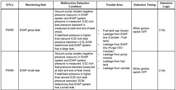
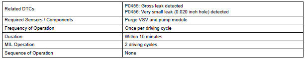
DTC P0455 Evaporative Emission Control System Leak Detected (Gross Leak)
DTC P0456 Evaporative Emission Control System Leak Detected (Very Small Leak)
DTC SUMMARY
DESCRIPTION
The circuit description can be found in the EVAP (Evaporative Emission) System.
INSPECTION PROCEDURE
Refer to the EVAP System.
MONITOR DESCRIPTION
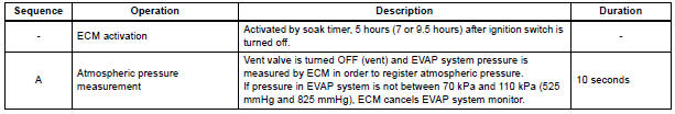
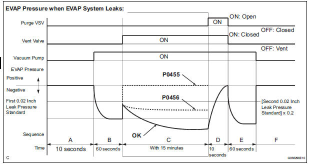
5 hours*1 after the ignition switch is turned off, the electric vacuum pump creates negative pressure (vacuum) in the EVAP (Evaporative Emission) system. The ECM monitors for leaks and actuator malfunctions based on the EVAP pressure.
HINT: *1: If the engine coolant temperature is not below 35C (95F) 5 hours after the ignition switch is turned off, the monitor check starts 2 hours later. If it is still not below 35C (95F) 7 hours after the ignition switch is turned off, the monitor check starts 2.5 hours later.
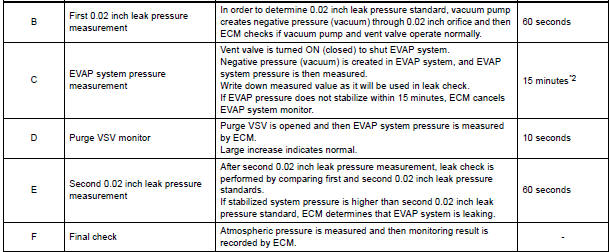
*2: If only a small amount of fuel is in the fuel tank, it takes longer for the EVAP pressure to stabilize.
- P0455: EVAP (Evaporative Emission) gross leak
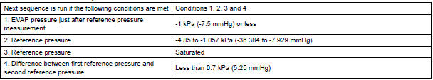
In operation C, the vacuum pump creates negative pressure (vacuum) in the EVAP system and the EVAP system pressure is measured. If the stabilized system pressure is higher than [second 0.02 inch leak pressure standard x 0.2] (near atmospheric pressure), the ECM determines that the EVAP system has a large leak, illuminates the MIL and sets the DTC (2 trip detection logic). - 2. P0456: EVAP very small leak
In operation C, the vacuum pump creates negative pressure (vacuum) in the EVAP system and the EVAP system pressure is measured. If the stabilized system pressure is higher than second 0.02 inch leak pressure standard, the ECM determines that the EVAP system has a small leak, illuminates the MIL and sets the DTC (2 trip detection logic).
MONITOR STRATEGY
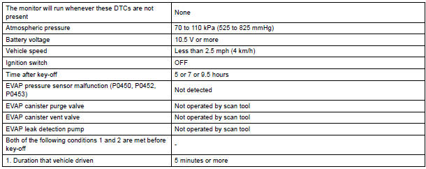
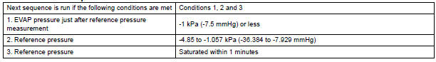
TYPICAL ENABLING CONDITIONS

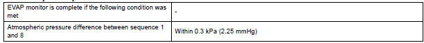
Key-off monitor sequence 1 to 8
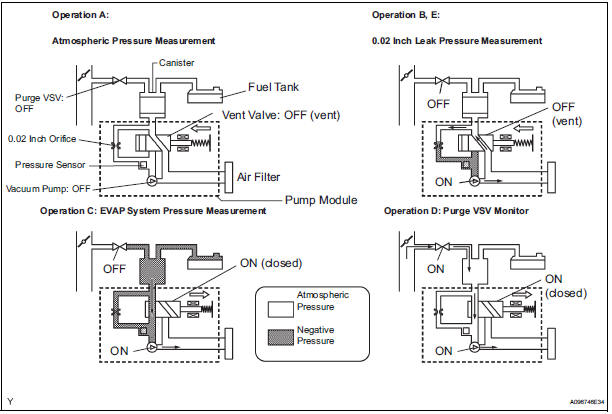
1. Atmospheric pressure measurement

2. First reference pressure measurement
3. EVAP canister vent valve close stuck check

4. Vacuum introduction

5. EVAP canister purge valve close stuck check

6. Second reference pressure measurement
7. Leak check

8. Atmospheric pressure measurement
TYPICAL MALFUNCTION THRESHOLDS
P0455: EVAP gross leak

P0456: EVAP 0.02 inch leak

MONITOR RESULT
Refer to CHECKING MONITOR STATUS
 Evaporative Emission Control System Pressure
DTC P0450 Evaporative Emission Control System Pressure
Sensor / Switch
DTC P0451 Evaporative Emission Control System Pressure
Sensor Range / Performance
DTC P0452 Evaporative Emission Control Syst ...
 Vehicle Speed Sensor "A"
DTC P0500 Vehicle Speed Sensor "A"
DESCRIPTION
The speed sensor detects the wheel speed and sends the appropriate signals to
the skid control ECU.
The skid control ECU converts these ...
Other materials:
Air Mix Damper Position Sensor Circuit (Passenger Side)
DESCRIPTION
This sensor detects the position of the air mix control servo motor (air mix
damper) and sends the
appropriate signals to the A/C amplifier. The position sensor is built in the
air mix control servo motor. The
position sensor's resistance changes as the air mix control servo m ...
Low Battery Positive Voltage
DTC C1241/41 Low Battery Positive Voltage
DESCRIPTION
If there is a problem with the brake actuator assembly (skid control ECU)
power supply circuit, the skid
control ECU outputs the DTC and prohibits the ABS operation with the fail safe
function.
If the voltage supplied to the IG1 termina ...
Inspection
1. INSPECT FRONT STABILIZER LINK ASSEMBLY LH
(a) As shown in the illustration, flip the ball joint stud
back and forth 5 times, before installing the nut.
(b) Using a torque wrench, turn the nut continuously at
a rate of 2 to 4 seconds per 1 turn and take the
torque reading on the 5th turn.
...
