Toyota Sienna Service Manual: For vehicles equipped with vehicle stability control (vsc) system
(a) Notices when using drum tester
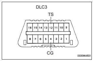
Notices when using drum tester.
(1) When using a drum tester, be sure to start the engine with the ignition switch OFF, and connect SST to the terminals TS and CG of the DLC3 before the measurement in order to cancel the VSC operation.
SST 09843-18040
(b) Notice of related operations to VSC
(1) Do not carry out unnecessary installation and removal as it might disorder the adjustment of the parts related to the VSC.
(2) Be sure to carry out the preparation for operation and the confirmation of operation completion in accordance with the instructions of the text and when the operations related to the VSC are performed.
 For vehicles equipped with traction control (trac) system
When using a 2-wheel drum tester such as a
speedometer tester or chassis dynamometer, etc., or
jacking up the front wheels and driving the wheels,
always push in the TRAC cut ("TRAC OFF") ...
 When towing full-time 4wd vehicles
Use one of the methods shown below to tow the
vehicle.
If the vehicle has trouble with the chassis or drive
train, use method 1 (flat bed truck).
WHEN TOWING FULL-TIME 4WD VEHICLES
...
Other materials:
Short in Driver Side Squib Circuit
DTC B0100/13 Short in Driver Side Squib Circuit
DESCRIPTION
The driver side squib circuit consists of the center airbag sensor assembly,
the spiral cable and the
steering pad. The circuit instructs the SRS to deploy when deployment conditions
are met. DTC B0100/13
is recorded when a short ci ...
Cooling fan ecu
ON-VEHICLE INSPECTION
1. INSPECT COOLING FAN ECU
(a) Inspect the input voltage.
(1) Disconnect the cooling fan ECU connector.
(2) Turn the ignition switch to the ON position.
Check the voltage of the +B terminal of the
disconnected wire harness side connector.
Standard voltage:
9 t ...
Insufficient Coolant Temperature for Closed
Loop Fuel Control
DTC P0125 Insufficient Coolant Temperature for Closed
Loop Fuel Control
DESCRIPTION
Refer to DTC P0115
DTC No.
DTC Detection Condition
Trouble Area
P0125
Engine coolant temperature (ECT) does not reach
closed-loop enabling temperature for 20 minutes (t ...
