Toyota Sienna Service Manual: Front Airbag Sensor RH Circuit Malfunction
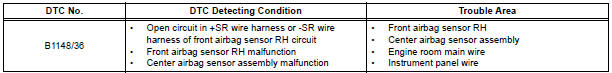
DTC B1148/36 Front Airbag Sensor RH Circuit Malfunction
DESCRIPTION
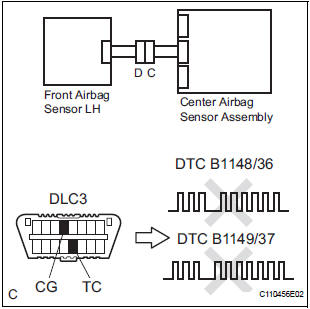
The front airbag sensor RH circuit consists of the center airbag sensor assembly and front airbag sensor RH. If the center airbag sensor assembly receives signals from the front airbag sensor RH, it judges whether or not the SRS should be activated.
DTC B1148/36 is recorded when a malfunction is detected in the front airbag sensor RH circuit.
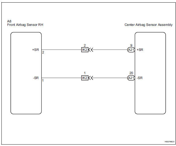
WIRING DIAGRAM
INSPECTION PROCEDURE
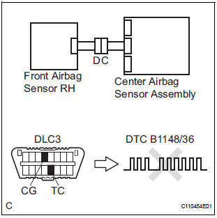
1 CHECK DTC
- Turn the ignition switch to the ON position, and wait for at least 60 seconds.
- Clear the DTCs stored in memory.
- Turn the ignition switch to the LOCK position.
- Turn the ignition switch to the ON position, and wait for at least 60 seconds.
- Check the DTCs.
OK: DTC B1148/36 is not output.
HINT: Codes other than DTC B1148/36 may be output at this time, but they are not related to this check.
USE SIMULATION METHOD TO CHECK
2 CHECK CONNECTION OF CONNECTORS
- Turn the ignition switch to the LOCK position.
- Disconnect the negative (-) terminal cable from the battery, and wait for at least 90 seconds.
- Check that the connectors are properly connected to the center airbag sensor assembly and the front airbag sensor RH.
OK: The connectors are connected.
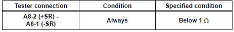
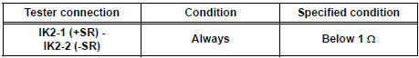
3 CHECK FRONT AIRBAG SENSOR RH CIRCUIT (OPEN)
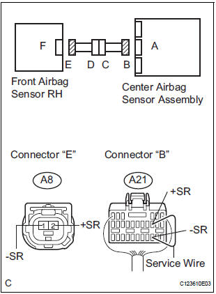
- Disconnect the connectors from the center airbag sensor assembly and the front airbag sensor RH.
- Using a service wire, connect A21-9 (+SR) and A21-20 (-
SR) of connector "B".
NOTICE: Do not forcibly insert a service wire into the terminals of the connector when connecting.
- Measure the resistance according to the value(s) in the table below.
Standard resistance
4 CHECK FRONT AIRBAG SENSOR RH
- Disconnect the service wire from connector "B".
- Connect the connector to the center airbag sensor assembly.
- Interchange the front airbag sensor RH with LH, and connect the connectors to them.
- Connect the negative (-) terminal cable to the battery, and wait for at least 2 seconds.
- Turn the ignition switch to the ON position, and wait for at least 60 seconds.
- Clear the DTCs stored in memory.
- Turn the ignition switch to the LOCK position.
- Turn the ignition switch to the ON position, and wait for at least 60 seconds.
- Check the DTCs.
Result
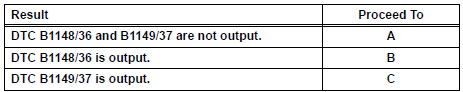
HINT: Codes other than DTC B1148/36 and B1149/37 may be output at this time, but they are not related to this check.
USE SIMULATION METHOD TO CHECK
5 CHECK INSTRUMENT PANEL WIRE (OPEN)
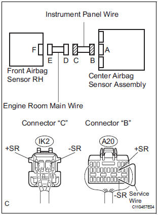
- Disconnect the instrument panel wire connector from the
engine room main wire.
HINT: The service wire has already been inserted into connector "B".
- Measure the resistance according to the value(s) in the table below.
Standard resistance
REPAIR OR REPLACE ENGINE ROOM MAIN WIRE
 Side Airbag Sensor Assembly LH Circuit Malfunction
DTC B1141/33 Side Airbag Sensor Assembly LH Circuit Malfunction
DESCRIPTION
The side airbag sensor LH circuit consists of the center airbag sensor
assembly and side airbag sensor
LH.
If the ce ...
 Front Airbag Sensor LH Circuit Malfunction
DTC B1149/37 Front Airbag Sensor LH Circuit Malfunction
DESCRIPTION
The front airbag sensor LH circuit consists of the center airbag sensor
assembly and front airbag sensor
LH.
If the center a ...
Other materials:
Terminals of ECU
1. CENTER AIRBAG SENSOR ASSEMBLY (w/ Side
Airbag)
2. CENTER AIRBAG SENSOR ASSEMBLY (w/o Side
Airbag)
...
Lost Communication with Radar Sensor
DTC U1102 Lost Communication with Radar Sensor
DESCRIPTION
The laser sensor and distance control ECU transmit the data for general
vehicle control and diagnosis
function along the communication line. The distance control ECU determines the
curve radius information
based on signals from the s ...
ON / OFF Indication Parameter Error
DTC 01-E2 ON / OFF Indication Parameter Error
DESCRIPTION
DTC No.
DTC Detection Condition
Trouble Area
01-E2
The command for ON/OFF control from the master
device has a problem.
Radio receiver
INSPECTION PROCEDURE
HINT:
After the inspection is ...
