Toyota Sienna Service Manual: Fuel Pump Primary Circuit
DTC P0230 Fuel Pump Primary Circuit
DESCRIPTION
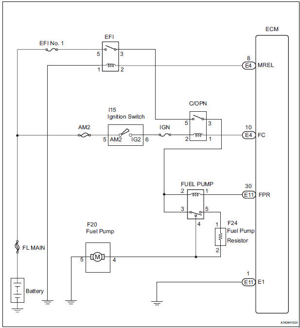
- This DTC is designed to detect a malfunction in the fuel pump (FUEL PUMP) relay circuit. When the system is normal, the battery voltage is applied to FPR terminal of the ECM while the FUEL PUMP relay is turned OFF. If the battery voltage is not applied to the FPR terminal while the FUEL PUMP relay is OFF, the ECM interprets this as a malfunction. The ECM then illuminates the MIL and sets a DTC.
- The FUEL PUMP relay switches the fuel pump speed according to the
engine conditions. The fuel
pump operates when the ECM receives the starter-operating signal (STA) and
crankshaft-rotating
signal (NE). The FUEL PUMP relay is turned ON while the engine is idling or
operating at low load.
This causes current to flow through the fuel pump resistor to the fuel pump. The fuel pump then operates at low speed. The FUEL PUMP relay is turned OFF while the engine is cranking or operating at high load. The fuel pump then operates at normal speed.
|
DTC No. |
DTC Detection Condition |
Trouble Area |
|
P0230 |
Open or short in FUEL PUMP relay circuit (1 trip detection logic) |
|
WIRING DIAGRAM
This troubleshooting procedure is based on the premise that the engine is started. If the engine is not started, proceed to the problem symptoms table.
INSPECTION PROCEDURE
1 PERFORM ACTIVE TEST BY INTELLIGENT TESTER
- Connect the intelligent tester to the DLC3.
- Turn the ignition switch to the ON position and turn the intelligent tester ON.
- Enter the following menus: DIAGNOSIS / ENHANCED OBD II / ACTIVE TEST / FUEL PUMP SP CTL.
- Check the operation of the relay while operating it using the intelligent tester.
OK: Operating noise can be heard from the relay.
2 INSPECT RELAY (FUEL PUMP RELAY)
- Remove the FUEL PUMP relay from the engine room junction block.
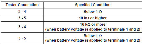
- Measure the resistance according to the value(s) in the table below.
Standard resistance
- Reinstall the FUEL PUMP relay.
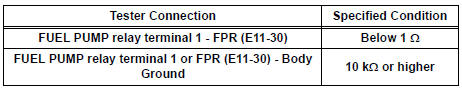
3 CHECK HARNESS AND CONNECTOR (FUEL PUMP RELAY - ECM)
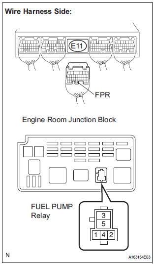
- Remove the FUEL PUMP relay from the engine room junction block.
- Disconnect the E11 ECM connector.
- Measure the resistance according to the value(s) in the table below.
Standard resistance
- Reconnect the ECM connector.
- Reinstall the FUEL PUMP relay
REPLACE ECM
 System Too Lean/ System Too Rich
DTC P0171 System Too Lean (Bank 1)
DTC P0172 System Too Rich (Bank 1)
DTC P0174 System Too Lean (Bank 2)
DTC P0175 System Too Rich (Bank 2)
DESCRIPTION
The fuel trim is related to the feedback co ...
 Random / Multiple Cylinder Misfire Detected/ Cylinder Misfire Detected
DTC P0300 Random / Multiple Cylinder Misfire Detected
DTC P0301 Cylinder 1 Misfire Detected
DTC P0302 Cylinder 2 Misfire Detected
DTC P0303 Cylinder 3 Misfire Detected
DTC P0304 Cylinder 4 Misfire ...
Other materials:
Readiness monitor drive
pattern
1. PURPOSE OF READINESS TESTS
The On-Board Diagnostic (OBD II) system is
designed to monitor the performance of emissionrelated
components, and indicate any detected
abnormalities with DTCs (Diagnostic Trouble Codes).
Since various components need to be monitored in
different d ...
Removal
1. REMOVE ROOF HEADLINING ASSEMBLY
2. REMOVE SLIDING ROOF SIDE GARNISH LH
Disengage the 3 claws.
Disengage the rear clip.
Disengage the front clip.
Remove the slide garnish by pulling it rearward.
3. REMOVE SLIDING ROOF SIDE GARNISH RH
HINT:
Use the same procedures described abov ...
Checking monitor status
The purpose of the monitor result (mode 06) is to allow
access to the results for on-board diagnostic monitoring tests
of specific components/systems that are not continuously
monitored. Examples are catalyst, evaporative emission
(EVAP) and thermostat.
The monitor result allows the OBD II sc ...
