Toyota Sienna Service Manual: Headlight dimmer switch
COMPONENTS

REMOVAL
1. REMOVE STEERING COLUMN LOWER COVER
2. REMOVE STEERING COLUMN UPPER COVER
3. REMOVE HEADLIGHT DIMMER SWITCH ASSEMBLY
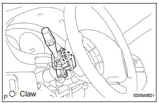
- Disconnect the connector.
- Release the claw fitting and remove the headlight dimmer switch assembly.
INSPECTION
1. HEADLIGHT DIMMER SWITCH ASSEMBLY
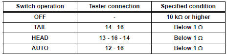
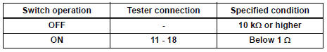
- Inspect light control switch resistance.
- Check that there is resistance between the terminals at each switch position as shown in the chart.
Resistance
- Inspect light control switch resistance.
- Check that there is resistance between the terminals at each switch position as shown in the chart.
Resistance
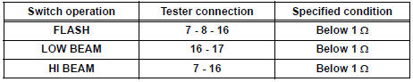
- Inspect light control switch resistance.
- Check that there is resistance between the terminals at each switch position as shown in the chart.
Resistance

- Inspect light control switch resistance.
- Check that there is resistance between the terminals at each switch position as shown in the chart.
Resistance
INSTALLATION
1. INSTALL HEADLIGHT DIMMER SWITCH ASSEMBLY
2. INSTALL STEERING COLUMN UPPER COVER
3. INSTALL STEERING COLUMN LOWER COVER
 Vanity light
ON-VEHICLE INSPECTION
1. LH VISOR ASSEMBLY
Inspect vanity light resistance.
check that the resistance exists between the
terminal 1 and the terminal 2 when the light is
oper ...
 Turn signal light switch
ON-VEHICLE INSPECTION
1. INSPECT TURN SIGNAL FLASHER CIRCUIT
Measure voltage between the terminals as shown in
the chart below.
Voltage
Connect the connector to turn the si ...
Other materials:
Reassembly
1. INSTALL REAR DOOR WIRE SUB-ASSEMBLY LH
Install the wire.
NOTICE:
When installing the wire, push the areas where
the clips are installed in order to prevent
damage and deformation.
Install the 2 screws.
2. INSTALL REAR DOOR LOCK ASSEMBLY LH
Apply MP grease to the slidi ...
Installation
1. INSTALL TIMING CHAIN CASE OIL SEAL
(a) Using SST, tap in a new oil seal until its surface is
flush with the timing chain case edge.
SST 09223-22010, 09506-35010
NOTICE:
Keep the lip free from foreign matter.
Do not tap on the oil seal at an angle.
Make sure that the oil ...
Removal
1. DRAIN AUTOMATIC TRANSAXLE FLUID (See page
AX-131)
2. REMOVE NO. 1 TRANSFER CASE PLUG (See page
TF-8)
3. REMOVE TRANSFER DRAIN PLUG
(a) Remove the transfer drain plug, gasket and bleed
the drain transfer oil.
4. REMOVE FRONT WHEEL
5. REMOVE FRONT DRIVE SHAFT ASSEMBLY RH
HINT:
(See page D ...
