Toyota Sienna Service Manual: High mounted stop light assembly
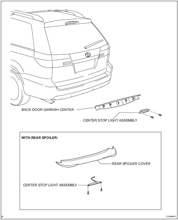
COMPONENTS
REMOVAL
1. REMOVE BACK DOOR GARNISH CENTER (w/ Rear Spoiler)
2. REMOVE REAR SPOILER COVER (w/ Rear Spoiler)
3. REMOVE CENTER STOP LIGHT ASSEMBLY
- w/o Rear spoiler:
- Disconnect the connector and remove the 2 screws and the center stop light assembly.
- w/ Rear spoiler:
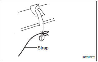
- Install the strap on the connector of the center stop light assembly.
- w/ Rear spoiler:
- Remove the 2 screws.
- w/ Rear spoiler:
- Pass the connector through the inside of the rear spoiler sub-assembly, and remove the center stop light assembly.
HINT: Leave the strap inside the rear spoiler subassembly.
INSTALLATION
1. INSTALL CENTER STOP LIGHT ASSEMBLY
2. INSTALL REAR SPOILER COVER
3. INSTALL BACK DOOR GARNISH CENTER
 License plate light assembly
COMPONENTS
REMOVAL
1. REMOVE BACK DOOR GARNISH CENTER
2. REMOVE BACK DOOR SIDE GARNISH LH
3. REMOVE BACK DOOR SIDE GARNISH RH
4. REMOVE BACK DOOR STRAP COVER
5. REMOVE BACK DOOR PULL STR ...
 Personal light assembly
ON-VEHICLE INSPECTION
1. ROOF CONSOLE BOX ASSEMBLY
Inspect map light assembly resistance.
Check the resistance between the terminals at
each switch position as shown in th ...
Other materials:
PCS (Pre-Collision
System)
When the radar sensor detects possibility of a frontal collision,
the pre-collision system such as the brakes and seat belts are
automatically engaged to lessen impact as well as vehicle damage.
Pre-collision warning
When a high possibility of a
frontal collision is detected, the
pre-colli ...
Installation
1. INSTALL SHOCK ABSORBER ASSEMBLY REAR LH
(a) Install the rear spring bumper No.1 LH to the shock
absorber assembly LH.
(b) Support the rear axle beam assembly with a jack.
(c) Install the rear shock absorber assembly rear LH,
cushion retainer and nut to the rear axle beam.
(d) ...
Power Slide Door Warning Buzzer LH does not Sound
DESCRIPTION
The power slide door system uses warning buzzers built into LH
slide doors respectively. Each buzzer
has 2 ways of sounding that are used differently according to the
situations.
When all the following conditions are met, the warning buzzer sounds at
a cycle of ...
