Toyota Sienna Service Manual: How to proceed with troubleshooting
The intelligent tester can be used in steps 4, 6, 8 and 9.
1 VEHICLE BROUGHT TO WORKSHOP
2 CUSTOMER PROBLEM ANALYSIS
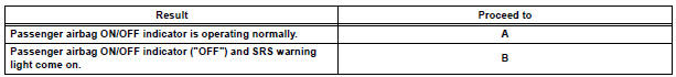
3 PASSENGER AIRBAG ON/OFF INDICATOR CHECK
4 DTCs CHECK (Present and Past DTCs)
- Check for DTCs.
Result

5 DTCs CHART
6 CIRCUIT INSPECTION
7 REPAIR
8 CLEAR DTCs (Present and Past DTCs)
- Clear DTCs
9 DTCs CHECK (Present and Past DTCs)
- Check for DTCs.
Result

10 SYMPTOM SIMULATION
- Check the passenger airbag ON/OFF indicator condition.
Result
11 CONFIRMATION TEST
END
 System description
1. DESCRIPTION OF OCCUPANT CLASSIFICATION SYSTEM
GENERAL DESCRIPTION.
In the occupant classification system, the
occupant classification ECU calculates the
weight of the occu ...
 Initialization
1. ZERO POINT CALIBRATION
NOTICE:
Make sure that the front passenger seat is not
occupied before performing the operation.
HINT:
Perform the zero point calibration and sensitivity check if
any ...
Other materials:
Terminals of ECU
1. CHECK TRANSPONDER KEY AMPLIFIER
Disconnect the I14 amplifier connector and measure
the resistance between the terminal of the wire
harness side connector and body ground.
If the result is not as specified, there may be a
malfunction on the wire harness side.
Reconnec ...
Optimal use of the audio
system
On the “Sound Settings” screen, sound quality (Treble/Mid/
Bass), volume balance can be adjusted.
How to adjust the sound settings and sound quality
1, 2, 3 Select “-” or “+” to adjust
the treble, mid or bass to
a level between -5 and 5.
4, 5 Select “Front” or “Rear” ...
Door LOCK Position Circuit
DESCRIPTION
This circuit detects the state of the door lock detection sensor and send it
to the Multiplex network body
ECU.
WIRING DIAGRAM
INSPECTION PROCEDURE
1 READ VALUE OF INTELLIGENT TESTER
Connect the intelligent tester to DLC3.
Turn the ignition switch ON and push the i ...
