Toyota Sienna Service Manual: How to use this manual
GENERAL INFORMATION
1. GENERAL DESCRIPTION
(a) This manual is written in accordance with SAE J2008.
(b) Repair operations can be separated mainly in the following 3 processes:
(1) Diagnosis
(2) Removing / Installing, Replacing, Disassembling / Reassembling, Checking and Adjusting
(3) Final Inspection
(c) The following procedures are omitted from this manual. However, these procedures must be performed.
(1) Use a jack or lift to perform operations
(2) Clean all removed parts
(3) Perform a visual check
2. INDEX
(a) An alphabetical INDEX section is provided at the end of the manual as a reference to help you find the item to be repaired.
3. PREPARATION
(a) Use of Special Service Tools (SST) and Special Service Materials (SSM) may be required, depending on the repair procedure. Be sure to use SST and SSM when they are required and follow the working procedure properly. A list of SST and SSM is in the "Preparation" section of this manual.
4. REPAIR PROCEDURES
(a) A component illustration is placed under the title where necessary. (b) Non-reusable parts, grease application areas, precoated parts and torque specifications are noted in the component illustrations. The following illustration is an example.
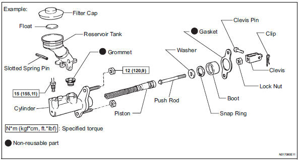
(c) Torque specifications, grease application areas and non-reusable parts are emphasized in th procedures.
HINT There are cases where such information can onl be explained by using an illustration. In these cases torque, oil and other information are described in th illustration
(d) Only items with key points are described in the text What to do and other details are explained usin illustrations next to the text. Both the text an illustrations are accompanied by standard value and notices.
(e) Illustrations of similar vehicle models are sometimes used. In these cases, minor details may be different from the actual vehicle.
(f) Procedures are presented in a step-by-step format.
5. SERVICE SPECIFICATIONS
(a) SPECIFICATIONS are presented in boldface text throughout the manual. The specifications are also found in the "Service Specifications" section for reference.
6. TERM DEFINITIONS

7. INTERNATIONAL SYSTEM OF UNITS
(a) The units used in this manual comply with the International System of Units (SI UNIT) standard.
Units from the metric system and the English systems are also provided.
Example:
Torque: 30 N*m (310 kgf*cm, 22 ft.*lbf)
 Introduction
...
 Identification information
VEHICLE IDENTIFICATION AND SERIAL NUMBERS
1. VEHICLE IDENTIFICATION NUMBER
(a) The vehicle identification number is stamped on the
vehicle identification number plate and the
certification label, ...
Other materials:
Engine Coolant Temperature Circuit Range / Performance Problem
DESCRIPTION
Refer to DTC P0115 (See page ES-133).
MONITOR DESCRIPTION
The ECT sensor is used to monitor the ECT. The ECT sensor has a built-in
thermistor with a resistance
that varies according to the temperature of the engine coolant. When the ECT
becomes low, the
resistance of the ...
Symptom simulation
HINT:
The most difficult case in troubleshooting is when no
problem symptoms occur. In such a case, a thorough
problem analysis must be carried out. A simulation of the
same or similar conditions and environment in which the
problem occurred in the customer's vehicle should be
carried out. No ...
Axle
SST
RECOMMENDED TOOLS
HINT:
Trox is a registered trademark of Trxtron Inc.
EQUIPMENT
...
