Toyota Sienna Service Manual: IG Power Source Circuit
DESCRIPTION
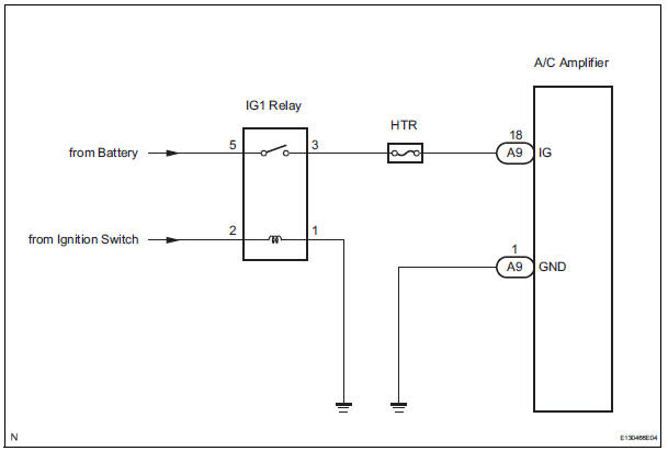
The main power source is supplied to the A/C amplifier when the ignition switch is turned to the ON position.
The power source is used for operating the A/C amplifier and servo motor, etc.
WIRING DIAGRAM
INSPECTION PROCEDURE
HINT: Start the engine before inspection. Check the IG1 relay or battery if the engine does not start.
1 INSPECT FUSE (HTR)
(a) Remove the HTR fuse from the driver side junction block.
(b) Measure the resistance according to the value(s) in the table below.
Standard resistance 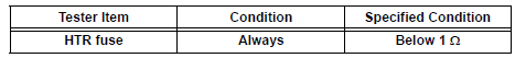


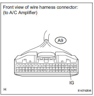
2 INSPECT A/C AMPLIFIER (IG - GND)
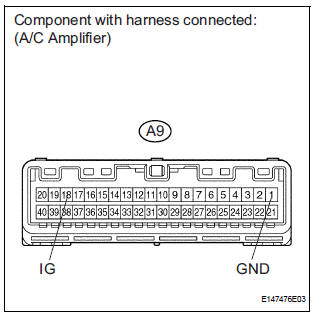
(a) Remove the A/C amplifier with its connectors still connected.
(b) Turn the ignition switch to the ON position.
(c) Measure the voltage according to the value(s) in the table below.
Standard voltage 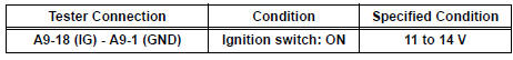


PROCEED TO NEXT CIRCUIT INSPECTION SHOWN IN PROBLEM SYMPTOMS TABLE
3 CHECK HARNESS AND CONNECTOR (A/C AMPLIFIER - BATTERY)
(a) Disconnect the connector from the A/C amplifier.
(b) Measure the voltage according to the value(s) in the table below.
Standard voltage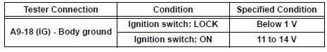

4 CHECK HARNESS AND CONNECTOR (A/C AMPLIFIER - BODY GROUND)
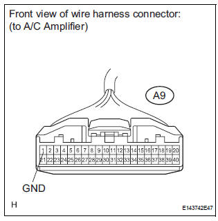
(a) Measure the resistance according to the value(s) in the table below.
Standard resistance 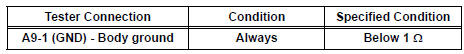

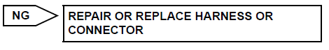
REPLACE A/C AMPLIFIER
 Rear Blower Motor Circuit
DESCRIPTION
Power to the rear blower motor is supplied from the battery via the RR A/C
relay.
The rear blower motor speed level varies between 0 and 31 based on the voltage
difference measured ...
 ACC Power Source Circuit
DESCRIPTION
This circuit supplies power to the A/C amplifier and the illumination for the
clock.
WIRING DIAGRAM
INSPECTION PROCEDURE
1 INSPECT FUSE (ECU ACC)
(a) Remove the ECU ACC fuse fr ...
Other materials:
Open in Front Passenger Side Squib Circuit
DTC B0106/54 Open in Front Passenger Side Squib Circuit
DESCRIPTION
The front passenger side squib circuit consists of the center airbag sensor
assembly and the front
passenger airbag assembly.
The circuit instructs the SRS to deploy when deployment conditions are met.
DTC B0106/54 is rec ...
Cruise Main Indicator Light Circuit
DESCRIPTION
The ECM detects a cruise control switch signal and sends it to the
combination meter through CAN
and BEAN. Then the CRUISE main indicator light comes on.
The CRUISE main indicator light circuit uses CAN and BEAN for
communication. If there is a
malfunction in ...
Problem symptoms table
SLIDING ROOF SYSTEM
Symptom
Suspected area
AUTO function does not operate
Sliding roof motor assembly
Sliding roof system does not operate
ECU-IG fuse
S/ Roof fuse
IG1 relay
Sliding roof housing assembly
Sliding roof motor switc ...
