Toyota Sienna Service Manual: Ignition Switch Circuit
DESCRIPTION
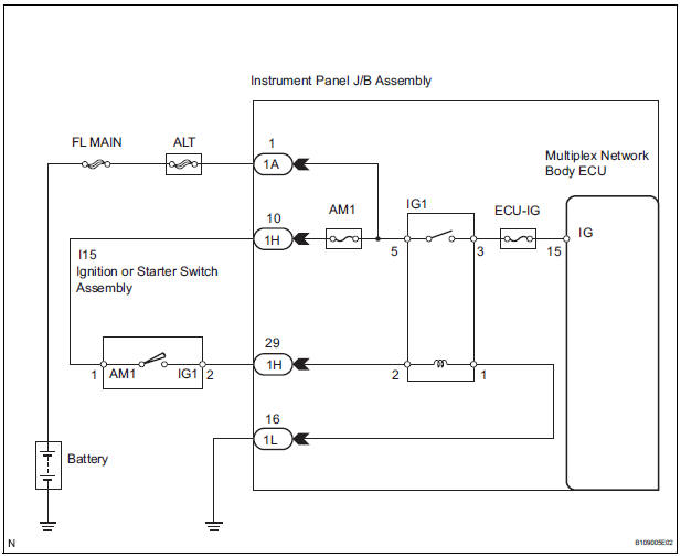
When the ignition switch is turned to the ON position, battery positive voltage is applied to terminal IG of the ECU. When battery positive voltage is applied to terminal IG of the ECU while the theft deterrent system is operating, the warning stops.
WIRING DIAGRAM
INSPECTION PROCEDURE
1 INSPECT FUSES (ECU-IG, AM1)
- Remove the ECU-IG and AM1 fuses from the instrument panel J/B.
- Measure the resistance.
Standard resistance: Below 1 Ω
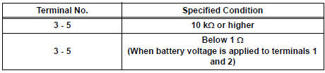
2 INSPECT RELAY (IG1)
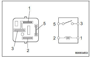
- Remove the IG1 relay from the instrument panel J/B.
- Check the operation of the IG1 relay.
Standard resistance
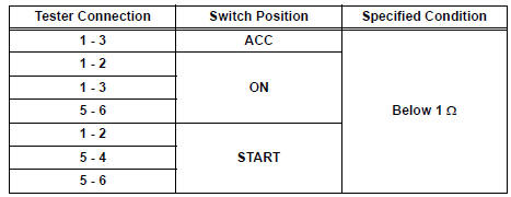
3 INSPECT IGNITION OR STARTER SWITCH ASSEMBLY
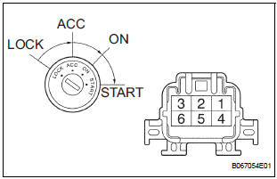
- Disconnect the I15 switch connector.
- Measure the resistance according to the value(s) in the table below.
Standard resistance
4 CHECK INSTRUMENT PANEL JUNCTION BLOCK ASSEMBLY (POWER SOURCE)
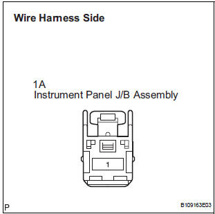
- Disconnect the 1A J/B connector.
- Turn the ignition switch ON.
- Measure the voltage according to the value(s) in the table below.
Standard voltage
REPLACE INSTRUMENT PANEL J/B ASSEMBLY
 Security Horn Circuit
DESCRIPTION
During the alarm sounding state, the relay in the ECU turns on and off in a
cycle of approximately 0.2
seconds, causing the security horn to sound.
WIRING DIAGRAM
INSPECTION PROC ...
 Security Indicator Light Circuit
DESCRIPTION
Even when the theft deterrent system is in the disarmed state, the security
indicator blinks due to a signal
output from the immobiliser system. The security indicator blinks continuou ...
Other materials:
A/C ECU Communication Stop
DTC B1262 A/C ECU Communication Stop
DESCRIPTION
DTC B1262 is output when communication between the A/C amplifier and the
multiplex network gateway
ECU stops for more than 10 seconds.
DTC No.
DTC Detection Condition
Trouble Area
B1262
A/C ECU communicat ...
Data list / active test
HINT:
By accessing the DATA LIST displayed on the intelligent
tester, you can perform such functions as reading the values
of switches and sensors without removing any parts. Reading
the DATA LIST as the first step in troubleshooting is one
method to shorten labor time.
1. DATA LIST FOR CENTER ...
Rear Airbag Sensor RH Circuit Malfunction
DTC B1154/38 Rear Airbag Sensor RH Circuit Malfunction
DESCRIPTION
The rear airbag sensor RH circuit consists of the center airbag sensor
assembly and rear airbag sensor
RH.
If the center airbag sensor assembly receives signals from the rear airbag
sensor RH, it judges whether or
not the ...
