Toyota Sienna Service Manual: Ignition system
Parts location

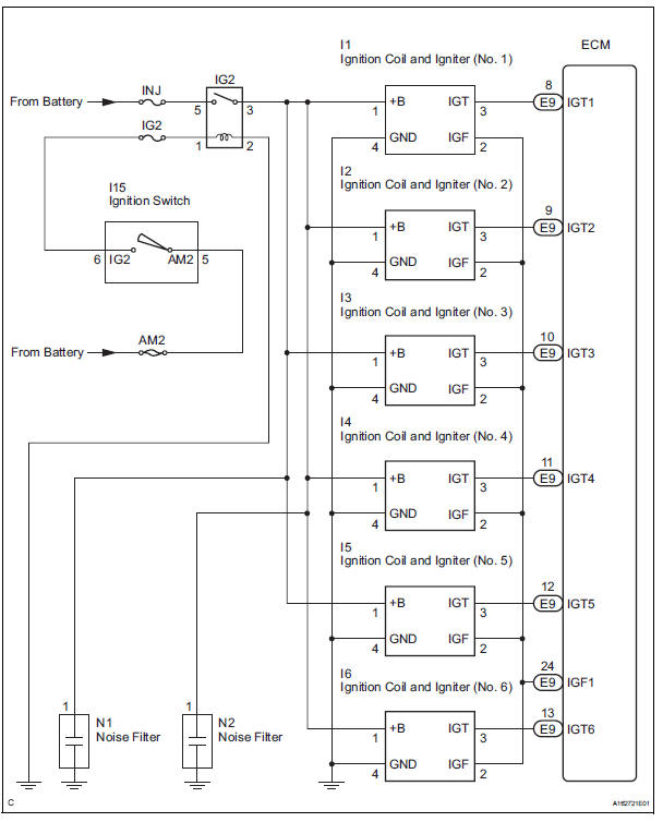
System diagram
 Engine
...
 Ignition coil and spark plug
Components
...
Other materials:
DTC check / clear
1. CHECK DTC
Connect the intelligent tester to the DLC3.
Connect the intelligent tester to the Controller
Area Network Vehicle Interface Module (CAN
VIM). Then connect the CAN VIM to the Data
Link Connector 3 (DLC3).
Turn the ignition switch to the ON posi ...
DVD Error/ Excess Current/ Tray Insertion / Ejection Error
DTC 44-44 DVD Error
DTC 44-48 Excess Current
DTC 44-50 Tray Insertion / Ejection Error
DESCRIPTION
DTC No.
DTC Detection Condition
Trouble Area
44-44
Operation error in the DVD mechanism
Television display assembly
44-48
Excess current is prese ...
Disposal
HINT:
When scrapping a vehicle equipped with the SRS or
disposing of the front passenger airbag assembly, be sure to
deploy the airbag first in accordance with the procedure
described below. If any abnormality occurs with airbag
deployment, contact the SERVICE DEPT. of the TOYOTA
MOTOR SALES, ...
