Toyota Sienna Service Manual: Illumination Circuit
DESCRIPTION
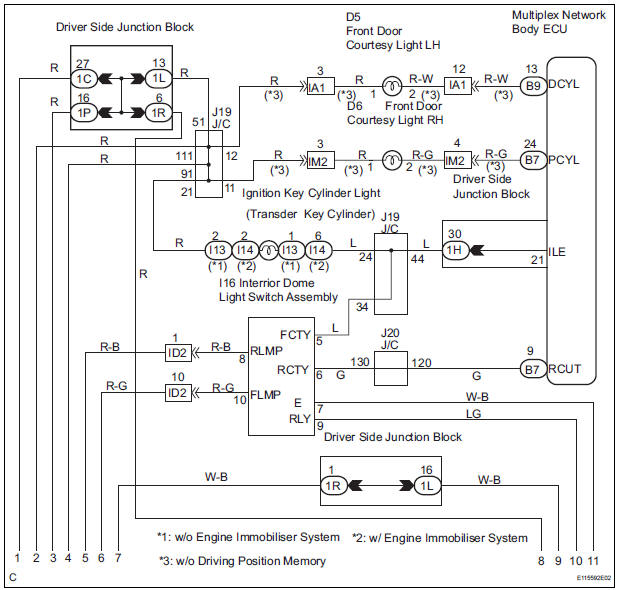
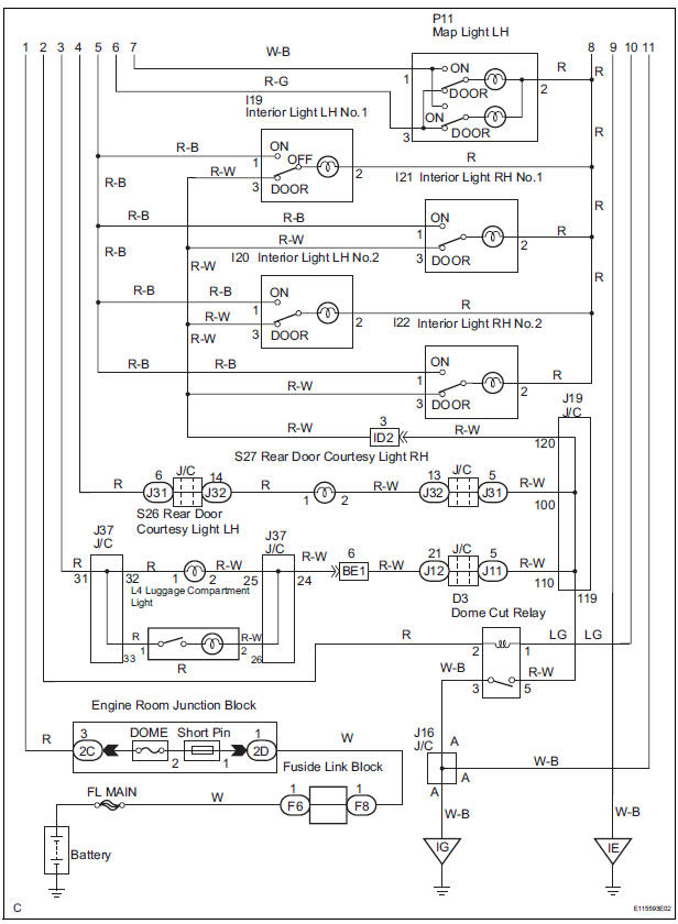
The Multiplex network body ECU controls illumination light as shown in the chart below.
- Room light assembly (Interior light, luggage component light) and courtesy light with DOOR position
- Map light assembly (Personal light)
- Transponder key amplifier (Ignition key cylinder light)
WIRING DIAGRAM
INSPECTION PROCEDURE
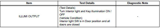
1 PERFORM ACTIVE TEST BY INTELLIGENT TESTER
- Connect the intelligent tester to DLC3.
- Turn the ignition switch ON and push the intelligent tester main switch ON.
- Select the item below in the ACTIVE TEST and then check that the relay operates
DATA LIST / AIR CONDITIONER
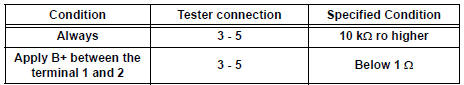
2 INSPECT LIGHT CONTROL RELAY
- Check that there is resistance between the terminals at each switch position as shown in the chart.
Resistance
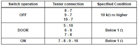
3 INSPECT INTERIOR DOME LIGHT SWITCH ASSEMBLY
- Inspect interior dome light relay continuity.
Resistance
4 INSPECT INTERIOR LIGHT
- Inspect the each of interior light
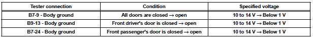
5 INSPECT INSTRUMENT PANEL JUNCTION BLOCK ASSEMBLY
- Measure voltage between each of the terminals as shown in the chart below
Voltage

PROCEED TO NEXT CIRCUIT INSPECTION SHOWN IN PROBLEM SYMPTOMS TABLE
 Door LOCK Position Circuit
DESCRIPTION
This circuit detects the state of the door lock detection sensor and send it
to the Multiplex network body
ECU.
WIRING DIAGRAM
INSPECTION PROCEDURE
1 READ VALUE OF INTELLIGENT T ...
 Parking Brake Switch Circuit
DESCRIPTION
The Multiplex network body ECU receives parking brake switch signal.
WIRING DIAGRAM
INSPECTION PROCEDURE
1 READ VALUE OF INTELLIGENT TESTER
Connect the intelligent tester to DL ...
Other materials:
DTC check / clear
1. CHECK DTC (USING INTELLIGENT TESTER)
Checking DTCs.
Connect the intelligent tester to the DLC3.
Turn the ignition switch ON.
Read DTCs by following the prompts on the
tester screen.
HINT:
Refer to the intelligent tester operator's manual
for furthe ...
Oxygen (A/F) Sensor Heater Control Circuit
HINT
Although the DTC titles say the oxygen sensor, these DTCs relate to the
Air-Fuel Ratio (A/F) sensor.
Sensor 1 refers to the sensor mounted in front of the Three-Way
Catalytic Converter (TWC) and
located near the engine assembly.
DESCRIPTION
Refer to DTC P2195 (See page ES- ...
Disassembly
1. REMOVE REAR DIFFERENTIAL CARRIER COVER
(a) Remove the 8 bolts from the carrier cover.
(b) Using a brass bar and a hammer, separate the
carrier cover from rear differential carrier assembly.
(c) Remove the breather plug from the rear differential
carrier cover.
(d) Remove the bol ...
