Toyota Sienna Service Manual: Initialization not Completed
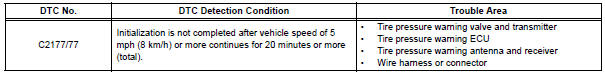
DTC C2177/77 Initialization not Completed
DESCRIPTION
Initialization is necessary after replacing any of the ECUs, tires with different tire pressure, or tire pressure warning valve and transmitter, after rotating the tires or when a new vehicle is delivered.
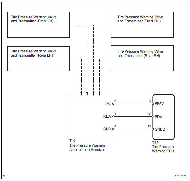
WIRING DIAGRAM
INSPECTION PROCEDURE
NOTICE:
- When replacing the tire pressure warning ECU, read the IDs stored in the old ECU using the intelligent tester and write them down before removal.
- It is necessary to perform initialization (See page TW-23) after registration (See page TW-20) of the transmitter IDs into the tire pressure warning ECU after the ECU and/or valve and transmitter have been replaced.
1 CHECK FREQUENCY RECEIVING CONDITION
(a) Check if the vehicle is not located in areas such as described below: (1) Facilities or devices that use similar radio frequencies are located in the vicinity of the vehicle.
HINT: If the vehicle is located in areas described above, the tire pressure warning light may come on after blinking 1 minute only in a particular area.
(2) Devices using similar radio frequencies are used in the vehicle.
OK: Facilities, or devices that use similar radio frequencies are not located in the vicinity of the vehicle.
HINT: Radio frequency may be interrupted due to surroundings or devices installed by the user.
2 IDENTIFY TRANSMITTER CORRESPONDING TO DTC
(a) Set the tire pressure to the appropriate specified values.
Cold tire inflation pressure
(b) Make sure that the ignition switch is off.
(c) Connect the intelligent tester to the DLC3.
(d) Turn the ignition switch to the ON position.
(e) Select "TIREPRESS" by following the prompts displayed on the intelligent tester.
TIRE PRESSURE:
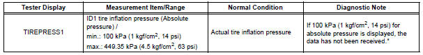
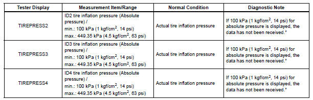
HINT: *: It may take about 5 to 6 minutes until the values are displayed. If the values are not displayed after a few minutes, perform troubleshooting according to the inspection procedure for DTCs C2121/21 to C2124/24 (See page TW-42).
(f) Rapidly reduce the tire pressure for each wheel at least 40 kPa (0.4 kg/cm2, 5.8 psi) within 30 seconds.
(g) Check the DATA LIST.
NOTICE:
- It takes about 5 to 6 minutes to display the updated tire pressure data.
- When no "TIREPRESS" data has changed, reset the tire pressure to the appropriate specified value and rotate the tire 90 to 270 degrees. Then rapidly release the tire pressure and recheck it.
- Record the transmitter ID of which "TIREPRESS" data corresponds to each tire.
(h) After confirming that one of "TIREPRESS" data for one tire (ID1 to ID4) has changed, repeat this procedure one by one. Identify the transmitter that corresponds to a DTC.
Result 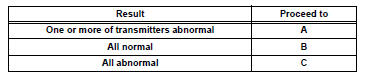

3 CHECK HARNESS AND CONNECTOR (ECU - RECEIVER)
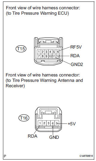
(a) Disconnect the T15 ECU connector.
(b) Disconnect the T16 receiver connector.
(c) Measure the resistance according to the value(s) in the table below.
Standard resistance 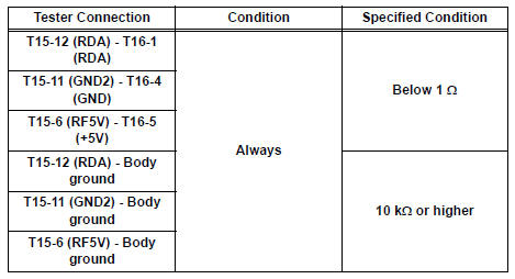


4 INSPECT TIRE PRESSURE WARNING VALVE AND TRANSMITTER
(a) Make sure that the ignition switch is off.
(b) Connect the intelligent tester to the DLC3.
(c) Turn the ignition switch to the ON position.
(d) Select REGIT ID CODE by following the prompts displayed on the intelligent tester.
TIRE PRESSURE: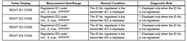
(e) Check the ID number on the identified transmitter by removing it from the tire and wheel.
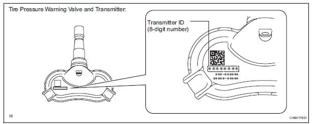
(f) Confirm that the ID number on the transmitter and recorded transmitter ID match.
Result 

5 REPLACE TIRE PRESSURE WARNING VALVE AND TRANSMITTER
(a) Replace the tire pressure warning valve and transmitter (See page TW-84).

6 REGISTRATION OF TRANSMITTER ID
(a) Perform registration (See page TW-20).

7 PERFORM INITIALIZATION
(a) Perform initialization (See page TW-23).

8 READ VALUE ON DATA LIST
(a) Make sure that the ignition switch is off.
(b) Connect the intelligent tester to the DLC3.
(c) Turn the ignition switch to the ON position.
(d) Select "TIREPRESS" by following the prompts displayed on the intelligent tester.
TIRE PRESSURE: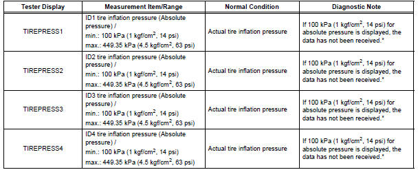
HINT: *: It may take about 5 to 6 minutes until the values are displayed. If the values are not displayed after a few minutes, perform troubleshooting according to the inspection procedure for DTCs C2121/21 to C2124/24 (See page TW-42).
Result

9 REPLACE TIRE PRESSURE WARNING ANTENNA AND RECEIVER
(a) Replace the tire pressure warning antenna and receiver (See page TW-81).

10 READ VALUE ON DATA LIST
(a) Make sure that the ignition switch is off.
(b) Connect the intelligent tester to the DLC3.
(c) Turn the ignition switch to the ON position.
(d) Select "TIREPRESS" by following the prompts displayed on the intelligent tester.
TIRE PRESSURE: 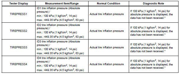
HINT: *: It may take about 5 to 6 minutes until the values are displayed. If the values are not displayed after a few minutes, perform troubleshooting according to the inspection procedure for DTCs C2121/21 to C2124/24 (See page TW-42).
Result 

END
 Receiver Error
DTC C2176/76 Receiver Error
DESCRIPTION
The signals are transmitted to the tire pressure warning antenna and receiver
on the body as radio waves
and then sent to the tire pressure warning ECU.
...
 Vehicle Speed Signal Error (Test Mode DTC)
DTC C2191/91 Vehicle Speed Signal Error (Test Mode DTC)
DESCRIPTION
The tire pressure warning ECU receives a speed signal from the combination
meter. This DTC is stored
upon entering test mode, a ...
Other materials:
TS and CG Terminal Circuit
DESCRIPTION
The Test Mode (signal check) circuit detects trouble in the sensor or switch
signal, which cannot be
detected by the DTC check.
Connecting terminals TS and CG of the DLC3 starts the check.
WIRING DIAGRAM
INSPECTION PROCEDURE
1 CHECK HARNESS AND CONNECTOR (BETWEEN SKID CONTR ...
Diagnosis system
1. DESCRIPTION
Front power seat control system data can be read
through the Data Link Connector 3 (DLC3) of the
vehicle. When the system seems to be
malfunctioning, use the intelligent tester to check for
malfunctions and perform repairs.
2. CHECK DLC3
The vehicle us ...
Customize parameters
HINT:
The following items can be customized.
NOTICE:
When the customer requests a change in a function,
first make sure that customization of the function(s) is
possible.
Be sure to record the current settings before
customizing.
When troubleshooting a function, fir ...
