Toyota Sienna Service Manual: Inspection
1. INSPECT REAR SPEED SENSOR
(a) Remove the seat cushion and seatback.
(b) Disconnect the speed sensor connector.
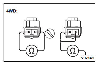
(c) Measure the resistance between terminals 1 and 2 of the speed sensor connector
OK: Resistance: 1.1 +- 0.2 kΩ at 25 +- 5 °C
(d) Measure the resistance between each of terminals 1 and 2 of skid control sensor connector and body ground.
OK: Resistance: 1 MΩ or higher
NOTICE: Check the speed sensor signal last (See page BC-10).
 Removal
HINT:
Remove the RH side by the same procedure as the LH side.
1. REMOVE REAR WHEEL
2. REMOVE QUARTER TRIM PANEL ASSEMBLY
FRONT LH
HINT:
Remove the LH side by the same procedure as the RH
side ...
 Installation
HINT:
Install the RH side by same procedure as the LH side.
1. INSTALL REAR SPEED SENSOR
(a) Install the speed sensor rear LH with the bolt.
Torque: 8.0 N*m (82 kgf*cm, 71 in.*lbf)
NOTICE:
K ...
Other materials:
For manual air conditioning system
ON-VEHICLE INSPECTION
1. INSPECT AIR INLET CONTROL SERVO MOTOR
(a) Remove the air inlet control servo motor.
(b) Connect the positive (+) lead from the battery to
terminal 5 and negative (-) lead to terminal 1, then
check that the lever turns to "RECIRCULATION"
side smoothly.
...
Rear Door ECU RH Communication Stop
DTC B1216 Rear Door ECU RH Communication Stop
DESCRIPTION
DTC B1216 is output when communication between the power slide door ECU RH
and the multiplex
network gateway ECU stops for more than 10 seconds.
DTC No.
DTC Detection Condition
Trouble Area
B1216
...
Microphone Circuit between Microphone and Radio and Navigation
Assembly
DESCRIPTION
This circuit sends a microphone signal from the microphone to the radio and
navigation assembly.
It also supplies power from the radio and navigation assembly to the microphone.
WIRING DIAGRAM
INSPECTION PROCEDURE
1 INSPECT RADIO AND NAVIGATION ASSEMBLY
Measure the v ...
