Toyota Sienna Service Manual: Inspection
1. INSPECT MAGNETIC CLUTCH CLEARANCE
(a) Set the dial indicator to the magnetic clutch hub.
(b) Connect the battery positive lead to the terminal 1 of the magnet clutch connector and the negative lead to the earth wire. Turn on and off the magnetic clutch and measure the clearance.
Standard clearance: 0.35 to 0.60 mm (0.013 to 0.023 in.)
If the measured value is not within the standard range, remove the magnetic clutch hub and adjust it with the magnetic clutch washers.
NOTICE: Adjustment can be performed with 3 or less magnetic clutch washers.
2. INSPECT COMPRESSOR OIL
(a) When replacing the compressor and magnetic clutch with a new one, after gradually removing the refrigerant gas from the service valve, drain the following amount of oil from the new compressor and magnetic clutch before installation.
Standard: (Oil capacity inside new compressor and magnetic clutch: 225 + 15 cc (7.6 + 0.5 fl.oz.)) - (Remaining oil amount in the removed compressor and magnetic clutch) = (Oil amount to be removed when replacing)
NOTICE:
- When checking the compressor oil level, observe the precautions on the cooler removal / installation.
- Because compressor oil remains in the pipes of the vehicle, if a new compressor and magnetic clutch is installed without removing some oil inside, the oil amount becomes excessive, preventing heat exchange in the refrigerant cycle and causing refrigerant failure.
- If the remaining oil in the removed compressor and magnetic clutch is too small in volume, check for oil leakage.
- Be sure to use ND-OIL 8 for compressor oil.
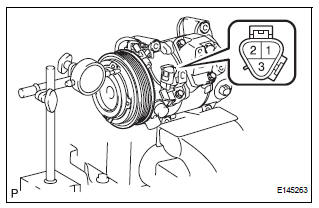
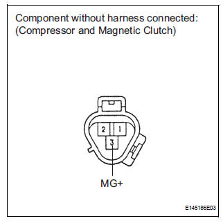
3. INSPECT COMPRESSOR AND MAGNETIC CLUTCH
(a) Disconnect the connector from the compressor and magnetic clutch.
(b) Disconnect the connector from the magnetic clutch.
(c) Measure the resistance according to the value(s) in the table below.
Standard resistance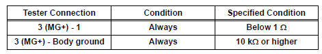
If the resistance is not as specified, replace the compressor and magnetic clutch.
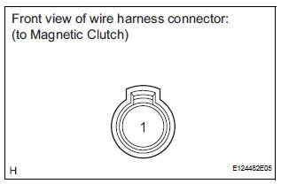
4. INSPECT MAGNETIC CLUTCH
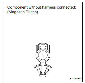
(a) Measure the resistance according to the value(s) in the table below.
Standard resistance 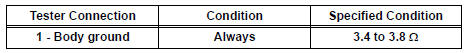
(b) When connector terminal A1 is connected to the positive (+) battery terminal, check that the following occurs: 1) the magnetic clutch's operating sound can be heard, and 2) the magnetic clutch's hub and rotor lock.
If the result is not as specified, replace the magnetic clutch.
 Disassembly
1. REMOVE MAGNETIC CLUTCH ASSEMBLY
(a) Place the compressor and magnetic clutch in a vise.
(b) Using locking pliers, hold the magnetic clutch hub.
(c) Remove the bolt, magnetic clutch hub, and
...
 Reassembly
1. INSTALL MAGNETIC CLUTCH ASSEMBLY
(a) Install the magnetic clutch stator while aligning the
protrusion on the stator with the notch on the air
compressor assembly as shown in the illustration ...
Other materials:
Standard bolt
HOW TO DETERMINE BOLT STRENGTH
SPECIFIED TORQUE FOR STANDARD BOLTS
HOW TO DETERMINE NUT STRENGTH
HINT:
*: Nut with 1 or more marks on one side surface of the nut.
Use a nut with the same nut strength classification number
(or greater) as the bolt strength classification number ...
Slide door lock release motor
Inspection
1. INSPECT SLIDE DOOR LOCK RELEASE MOTOR ASSEMBLY LH
Apply battery voltage and inspect operation of the
motor.
OK
If the result is not as specified, replace the motor
assembly.
2. INSPECT SLIDE DOOR LOCK RELEASE MOTOR ASSEMBLY RH
Apply battery voltage and insp ...
Engine coolant temperature sensor
COMPONENTS
REMOVAL
1. DRAIN ENGINE COOLANT (See page CO-6)
2. REMOVE V-BANK COVER SUB-ASSEMBLY (See
page EM-28)
3. REMOVE NO. 2 AIR CLEANER INLET (See page EM-
28)
4. REMOVE NO. 1 AIR CLEANER INLET (See page EM-
28)
5. REMOVE AIR CLEANER CAP SUB-ASSEMBLY (See
page ES-493)
6. REMOVE AI ...
