Toyota Sienna Service Manual: Inspection
1. INSPECT FRONT SEAT INNER BELT ASSEMBLY RH
- Release the seat belt (Buckle switch is ON).
- Check the resistance between the terminals.
Standard
If the result is not as specified, replace the inner belt assembly.
- Inspect the buckle switch.
- Fasten the seat belt (Buckle switch is OFF).
- Check the resistance between the terminals.
Standard
- Inspect the circuit for the airbag seat position sensor.
- Check the resistance between the terminals.
Standard
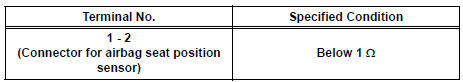
If the result is not as specified, replace the seat cushion assembly.
2. INSPECT FRONT SEAT INNER BELT ASSEMBLY LH
- Inspect the buckle switch.
- Fasten the seat belt (Buckle switch is ON).
- Check the resistance between the terminals.
Standard
- Release the seat belt (Buckle switch is OFF).
- Check the resistance between the terminals.
Standard
If the result is not as specified, replace the inner belt assembly.
 Removal
1. REMOVE FRONT SEAT INNER BELT ASSEMBLY
HINT:
Refer to the instructions for disassembly of the front
seat assembly (for flat type).
Refer to the instructions for disassembly of t ...
 Installation
1. REMOVE FRONT SEAT INNER BELT ASSEMBLY
HINT:
Refer to the instructions for reassembly of the front
seat assembly (for flat type).
Refer to the instructions for reassembly of the ...
Other materials:
Removal
HINT:
Use the same procedures for the RH side and LH side.
The procedures listed below are for the LH side.
1. PRECAUTION
CAUTION: Be sure to read "PRECAUTION" thoroughly before
servicing.
2. DISCONNECT CABLE FROM NEGATIVE BATTERY
TERMINAL
CAUTION:
Wait for 90 s ...
Power Source Circuit
DESCRIPTION
This is the power source circuit for the outer mirror control ECU.
WIRING DIAGRAM
INSPECTION PROCEDURE
1 INSPECT OUTER MIRROR CONTROL ECU (POWER SOURCE)
Disconnect the O9 or O11 ECU connector.
Measure the voltage and resistance according to the
value(s) in the t ...
Installation
1. INSTALL OUTSIDE MOULDING
Using a heat light, heat the mounting surface of the
vehicle body between 40 to 60 C (104 to 140 F).
NOTICE:
Do not heat the body excessively.
Remove the tape from the vehicle body.
Wipe off the stains with cleaner.
Clean the outside moulding (if reusing t ...
