Toyota Sienna Service Manual: Inspection
1. INSPECT HEATED OXYGEN SENSOR (for Bank 1 Sensor 2)
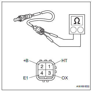
(a) Measure the resistance of the sensor.
Standard resistance
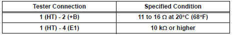
If the resistance is not as specified, replace the sensor.
2. INSPECT HEATED OXYGEN SENSOR (for Bank 2 Sensor 2)
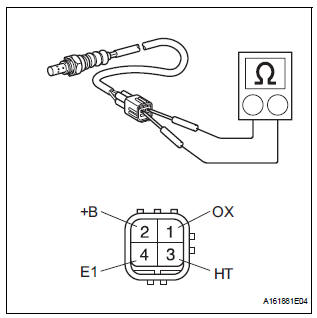
(a) Measure the resistance of the sensor.
Standard resistance
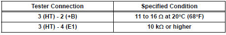
If the resistance is not as specified, replace the sensor.
Installation
1. INSTALL HEATED OXYGEN SENSOR (for Bank 2 Sensor 2)
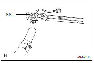
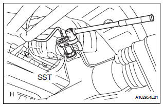
(a) Using SST, install the heated oxygen sensor to the front exhaust pipe.
SST 09224-00010
Torque: 40 N*m (408 kgf*cm, 30 ft.*lbf) for use with SST 44 N*m (449 kgf*cm, 32 ft.*lbf) for use without SST
HINT:
- Use a torque wrench with a fulcrum length of 30 cm (11.81 in.).
- Make sure that SST and a wrench are connected in a straight line.
2. INSTALL FRONT EXHAUST PIPE ASSEMBLY
(a) Check the compression springs.
(1) Check the compression springs using vernier calipers
Specified length: 38.86 mm (1.5299 in.)
HINT: If the result is not as specified, replace the compression spring.
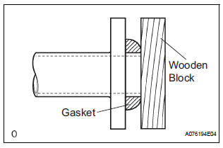
(b) Install the gasket.
(1) Install a new gasket by hand onto the front exhaust pipe assembly.
(2) Using a plastic hammer and wooden block, tap in the new gasket until its surface is flush with the front exhaust pipe.
NOTICE:
|
(c) Install 2 new gaskets to the front exhaust pipe assembly.
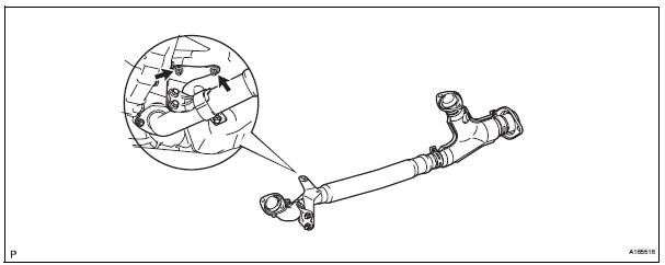
(d) Install the front exhaust pipe assembly with the 4 nuts.
Torque: 62 N*m (632 kgf*cm, 46 ft.*lbf)
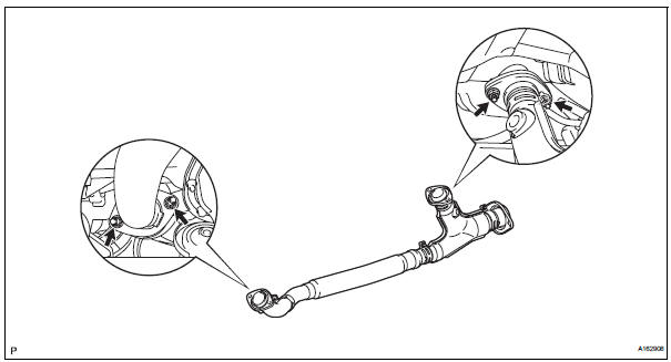
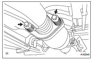
(e) Install the front exhaust pipe assembly with the 2 compression springs and 2 bolts.
Torque: 43 N*m (438 kgf*cm, 32 ft.*lbf) (f) Install the No. 1 exhaust pipe support bracket with 2 new nuts.
Torque: 21 N*m (214 kgf*cm, 15 ft.*lbf)
(g) Connect the heated oxygen sensor (for Bank 2 sensor 2) connector.
3. INSTALL HEATED OXYGEN SENSOR (for Bank 1 Sensor 2)
(a) Using SST, install the heated oxygen sensor.
SST 09224-00010
Torque: 40 N*m (408 kgf*cm, 30 ft.*lbf) for use with SST
44 N*m (449 kgf*cm, 32 ft.*lbf) for use without SST
HINT:
- Use a torque wrench with a fulcrum length of 30 cm (11.81 in.).
- Make sure that SST and a wrench are connected in a straight line.
b) Connect the heated oxygen sensor (for Bank 1 Sensor 2) connector.
4. CONNECT CABLE TO NEGATIVE BATTERY TERMINAL
5. INSPECT FOR EXHAUST GAS LEAK
 Heated oxygen sensor (for 2wd)
Components
Removal
1. DISCONNECT CABLE FROM NEGATIVE BATTERY
TERMINAL
CAUTION:
Wait at least 90 seconds after disconnecting the
cable from the nagative (-) battery terminal to
...
 Heated oxygen sensor (for 4wd)
Components
...
Other materials:
Parking Brake Switch Circuit
DESCRIPTION
This circuit is from the parking brake switch to the radio and navigation
assembly.
WIRING DIAGRAM
INSPECTION PROCEDURE
1 CHECK BRAKE WARNING LIGHT
Check that the brake warning light comes on when the
parking brake is applied and goes off when it is released.
OK:
The ...
Identification information
VEHICLE IDENTIFICATION AND SERIAL NUMBERS
1. VEHICLE IDENTIFICATION NUMBER
(a) The vehicle identification number is stamped on the
vehicle identification number plate and the
certification label, as shown in the illustration.
A:
Vehicle Identification Number Plate
B:
...
Disposal
HINT:
When scrapping a vehicle equipped with the SRS or
disposing of the steering pad, be sure to deploy the airbag
first in accordance with the procedure described below. If any
abnormality occurs with airbag deployment, contact the
SERVICE DEPT. of TOYOTA MOTOR SALES, U.S.A., INC.
CAUTION:
...
