Toyota Sienna Service Manual: Inspection
1. Inspect starter assembly
| NOTICE: These tests must be performed within 3 to 5 seconds to avoid burning out the coil. |
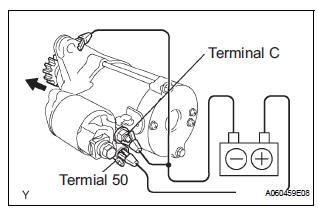
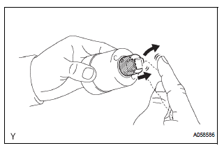
(a) Perform the pull-in test.
(1) Disconnect the lead wire from terminal C.
(2) Connect the battery to the magnetic switch as shown in the illustration. Check that the clutch pinion gear extends.
If the clutch pinion gear does not move, replace the magnetic switch.
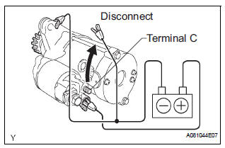
(b) Perform the hold-in test.
(1) Maintain the battery connections in step (a), but disconnect the negative (-) lead from terminal C. Check that the pinion gear remains extended.
If the clutch pinion gear returns inward, replace the magnetic switch.
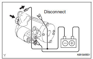
(c) Check the clutch pinion gear return.
(1) Disconnect the negative (-) lead from the switch body. Check that the clutch pinion gear returns.
If the clutch pinion gear does not return, replace the magnetic switch.
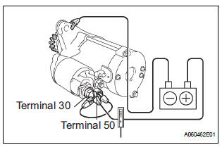
(d) Perform the no-load performance test.
(1) Connect the lead wire to terminal C. Make sure that the lead is not grounded.
(2) Clamp the starter in a vise.
(3) Connect the battery and an ammeter to the starter as shown in the illustration.
(4) Check that the starter rotates smoothly and steadily with the clutch pinion gear extended.
Check that the ammeter reads the specified current.
Specified current: 90 A or less at 11.5 V
2. INSPECT REPAIR SERVICE STARTER KIT
(a) Check the plunger.
(1) Push in the plunger and check that it returns quickly to its original position.
If necessary, replace the repair service starter kit.
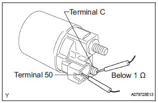
(b) Check if the pull-in coil has an open circuit.
(1) Measure the resistance between terminals 50 and C.
Resistance: Below 1 Ω
If the result is not as specified, replace the repair service starter kit.
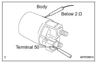
(c) Check if the hold-in coil has an open circuit.
(1) Measure the resistance between terminal 50 and the switch body.
Resistance: Below 2 Ω
If the result is not as specified, replace the repair service starter kit.
3. INSPECT STARTER ARMATURE ASSEMBLY
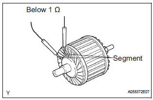
(a) Measure if the commutator has an open circuit.
(1) Check the resistance between the segments of the commutator.
Resistance: Below 1 Ω
If the result is not as specified, replace the armature assembly.
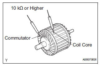
(b) Check if the commutator is grounded.
(1) Measure the resistance between the commutator and armature coil core.
Resistance: 10 kΩ or higher
If the result is not as specified, replace the armature assembly
(c) Check the commutator for contamination and burns on its surface.
If the surface is dirty or burnt, correct it with sandpaper (No. 400) or a lathe.
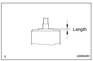
(d) Using a vernier caliper, measure the commutator's length.
Standard length: 3.3 to 4.0 mm (0.1299 to 0.1575 in.) If the length is greater than the maximum, replace the starter armature.
4. INSPECT STARTER COMMUTATOR END FRAME ASSEMBLY
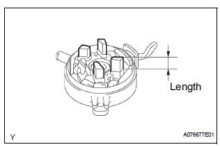
(a) Using a vernier caliper, measure the brush length.
Specified length: 4.0 to 9.0 mm (0.158 to 0.354 in.) If the length is less than the minimum, replace the starter commutator end frame.
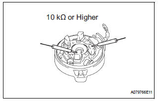
(b) Check the brush insulation.
(1) Measure the resistance between the positive (+) and negative (-) brush.
Resistance: 10 kΩ or higher If the result is not as specified, repair or replace starter commutator end frame.
5. INSPECT REPAIR SERVICE STARTER KIT
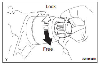
(a) Check the starter clutch.
(1) Rotate the clutch pinion gear counterclockwise and check that it turns freely. Try to rotate the clutch pinion gear clockwise and check that it locks.
If necessary, replace the service starter kit.
 Disassembly
1. Remove repair service starter kit
(a) Remove the nut and disconnect the lead wire from
the repair service starter kit.
(b) Remove the 2 screws which are used to secure the
repair servic ...
 Reassembly
1. INSTALL PLANETARY GEAR
(a) Apply grease to the planetary gears and pin parts of
the planetary shaft.
(b) Install the 3 planetary gears.
2. INSTALL STARTER ARMATURE ASSEMBLY
(a) Apply ...
Other materials:
Installation
1. INSTALL THROTTLE BODY
Install a new throttle body gasket to the intake air
surge tank.
Install the throttle body with the 4 bolts.
Torque: 10 N*m (102 kgf*cm, 7 ft.*lbf)
Connect the 2 water by-pass hoses.
Connect the throttle body connector and clamp.
2. ...
Vehicle exterior
Items
Check points
Doors
Do the doors operate smoothly?
Engine hood
Does the engine hood lock system work
properly?
Fluid leaks
There should not be any signs of fluid
leakage after the vehicle ha ...
Warning Buzzer Malfunction
DTC P1575 Warning Buzzer Malfunction
DESCRIPTION
The ABS & traction actuator (skid control ECU) receives an alarm demand
signal from the ECM and
operates the skid control buzzer. The buzzer sounds to warn that the distance
between the vehicle in front
and your own vehicle is decreasing.
...
