Toyota Sienna Service Manual: Inspection
1. INSPECT MULTIPLE DISC CLUTCH HUB
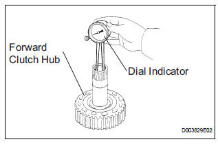
(a) Using a dial indicator, measure the inside diameter of the forward clutch hub bushing
Standard inside diameter: 23.025 to 23.046 mm (0.9065 to 0.9073 in.) Maximum inside diameter: 23.09 mm (0.9091 in.)
| NOTICE: Check the contact surface of the bushing in the direct clutch shaft. If any scratch or discoloration is found, replace the direct clutch sub-assembly with a new one. |
If the inside diameter is greater than the maximum, replace the forward clutch hub with a new one.
2. INSPECT UNDERDRIVE CLUTCH DISC NO.2
(a) Check if the sliding surfaces of the disc, plate and flange are worn or burnt.
If necessary, replace them.
NOTICE:
|
3. INSPECT OVERDRIVE DIRECT CLUTCH DRUM SUBASSEMBLY
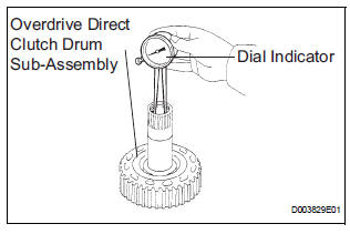
(a) Using a dial indicator, measure the inside diameter of the forward clutch hub bushing.
Standard inside diameter: 23.025 to 23.046 mm (0.9065 to 0.9073 in.) Maximum inside diameter: 23.09 mm (0.9091 in.)
| NOTICE: Check the contact surface of the bushing in the direct clutch shaft. If any scratch or discoloration is found, replace the direct clutch sub-assembly with a new one. |
If the inside diameter is greater than the maximum, replace the forward clutch hub with a new one.
4. INSPECT 2ND BRAKE CLUTCH DISC
(a) Check if the sliding surface of the disc, plate and flange are worn or burnt.
If necessary, replace them.
NOTICE:
|
5. INSPECT 1ST AND REVERSE BRAKE CLUTCH DISC
(a) Check if the sliding surface of the disc, plate and flange are worn or burnt.
If necessary, replace them.
NOTICE:
|
6. INSPECT 1ST AND REVERSE BRAKE RETURN SPRING SUB-ASSEMBLY
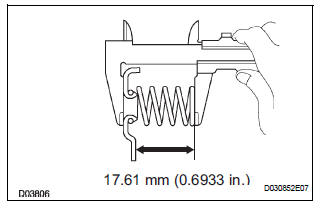
(a) Using a vernier calipers, measure the free length of the spring together with the spring seat.
Standard free length: 17.61 mm (0.6933 in.) HINT: If the result is not as specified, replace the spring.
7. INSPECT UNDERDRIVE BRAKE RETURN SPRING SUB-ASSEMBLY
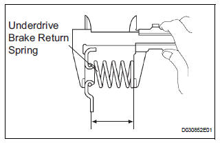
(a) Using a vernier calipers, measure the free length of the spring together with the spring seat.
Standard free length: 13.24 mm (0.5213 in.) HINT: If the result is not as specified, replace the spring.
8. INSPECT PACK CLEARANCE OF 1ST AND REVERSE BRAKE
(a) Using vernier calipers, measure the distance between the disc surface and the contact surface of the 2nd brake cylinder and transaxle case (Dimension A).
(b) Select an appropriate flange so that the pack clearance will meet the specified value.
Pack clearance: 1.16 to 1.35 mm (0.0457 to 0.0531 in.)
HINT: Piston stroke = Dimension A - Flange thickness
Flange thickness: mm (in.) 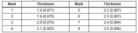
(c) Install the flange.
9. INSPECT PACK CLEARANCE OF 2ND BRAKE
(a) Using a vernier calipers, measure the distance between the disc surface and snap ring surface (Dimension B).
(b) Select an appropriate flange so that the pack clearance will meet the specified value.
Pack clearance: 0.62 to 0.91 mm (0.0244 to 0.0358 in.)
HINT: Piston stroke = Dimension B - Flange thickness - Snap ring thickness 1.6 mm (0.063 in.)
Flange thickness: mm (in.) 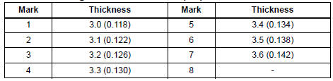
(c) Install the flange.
9. INSPECT PACK CLEARANCE OF 2ND BRAKE
(a) Using a vernier calipers, measure the distance between the disc surface and snap ring surface (Dimension B).
(b) Select an appropriate flange so that the pack clearance will meet the specified value.
Pack clearance: 0.62 to 0.91 mm (0.0244 to 0.0358 in.)
HINT: Piston stroke = Dimension B - Flange thickness - Snap ring thickness 1.6 mm (0.063 in.)
Flange thickness: mm (in.)
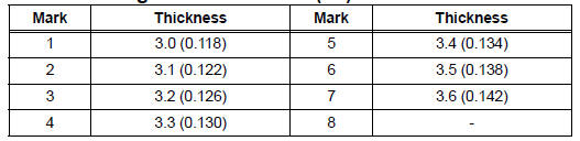
10. INSPECT PACK CLEARANCE OF UNDERDRIVE BRAKE
(a) Using a dial indicator, measure the underdrive brake pack clearance while applying and releasing compressed air (392 kPa, 4.0 kgf/cm2, 57 psi).
Pack clearance: 1.81 to 2.20 mm (0.0713 to 0.0866 in.)
HINT: Select an appropriate flange from the table below so that it will meet the specified value.
Flange thickness: mm (in.) 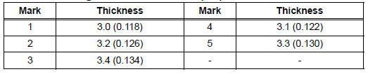
(b) Temporarily remove the snap ring and attach it to the flange.
(c) Reinstall the snap ring.
11. INSPECT UNDERDRIVE 1-WAY CLUTCH ASSEMBLY
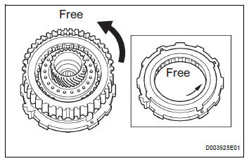
(a) Install the underdrive clutch assembly to the 1-way clutch.
(b) Rotate the underdrive 1-way clutch assembly to check the rotating direction for the lock or free operation.
HINT: If the result is not as specified, replace the underdrive 1-way clutch.
12. INSPECT INPUT SHAFT END PLAY
(a) Using a dial indicator, measure the input shaft end play.
End play: 0.262 to 1.244 mm (0.01 to 0.049 in.)
HINT: If the result is not as specified, replace the input shaft or thrust needle roller bearing.
 Disassembly
1. Remove park/neutral position switch assembly
(A) remove the nut, washer and control shaft lever.
(B) using a screwdriver, unstake the nut stopper, and
remove the lock nut and nut stopper ...
 Reassembly
1. BEARING POSITION
2. INSTALL DIFFERENTIAL GEAR LUBE APPLY TUBE
(a) Install the differential gear lube apply tube and
transaxle apply tube clamp with the bolt to the
transaxle housing ...
Other materials:
Terminals of ECU
1. CHECK INSTRUMENT PANEL J/B ASSEMBLY
(MULTIPLEX NETWORK BODY ECU)
Disconnect the B6, B7 and B9 ECU connectors.
Disconnect the 1A, 1C, 1L and 1K J/B connectors.
Measure the voltage and resistance between each
terminal of the wire harness side connectors and
body gro ...
On-vehicle inspection
1. CHECK RADIATOR RESERVOIR CAP SUBASSEMBLY
a) Measure the valve opening pressure.
(1) If there are water stains or foreign matter on
rubber packings 1, 2 or 3, clean the part(s) with
water and finger scouring.
(2) Check that rubber packings 1, 2 and 3 are not
deformed, cracked or swol ...
Inspection
1. Inspect generator clutch pulley
(a) Hold the center of the pulley, and confirm that the
outer ring turns counterclockwise and does not turn
clockwise.
If the result is not as specified, replace the clutch
pulley.
2. Remove generator drive end frame bearing
(a) Check that the bear ...
