
Toyota Sienna Service Manual: Inspection
1. Inspect pack clearance of reverse clutch
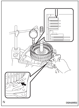
(A) install the intermediate shaft and needle roller bearing onto the transaxle rear cover.
(B) using a dial indicator, measure the reverse clutch pack clearance while applying and releasing compressed air (392 kpa, 4.0 Kgf/cm2, 57 psi).
Pack clearance: 0.60 To 0.82 Mm (0.02362 To 0.03228 In.)V
If the pack clearance is not as specified, inspect the discs, plates and flange.
2. Inspect pack clearance of direct clutch and overdrive clutch
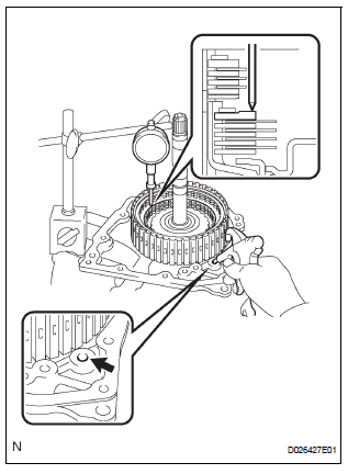
(a) Using a dial indicator, measure the direct clutch and overdrive clutch pack clearance while applying and releasing compressed air (392 kPa, 4.0 kgf/cm2, 57 psi).
Pack clearance: 0.61 to 0.83 mm (0.02401 to 0.03268 in.)
If the pack clearance is not as specified, inspect the discs, plates and flange.
3. INSPECT DIRECT MULTIPLE DISC CLUTCH DISC
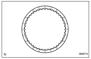
(a) Check if the sliding surfaces of the disc, plate and flange are worn or burnt.
If necessary, replace them.
HINT:
- If the lining of the disc comes off or discolors, or if a part of the groove is worn, replace all discs.
- Before installing new discs, immerse them in ATF for at least 15 minutes.
4. INSPECT OVERDRIVE DIRECT CLUTCH DISC
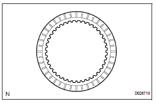
(a) Check if the sliding surface of the disc, plate and flange are worn or burnt.
If necessary, replace them.
HINT:
- If the lining of the disc comes off or discolors, or if a part of the groove is worn, replace all discs
- Before installing new discs, immerse them in ATF for at least 15 minutes.
5. INSPECT OVERDRIVE CLUTCH RETURN SPRING SUB-ASSEMBLY
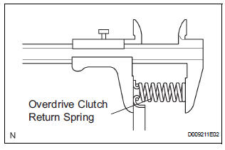
(a) Using vernier calipers, measure the free length of the spring together with the spring seat.
Standard free length: 25.91 mm (1.0201 in.)
6. INSPECT PACK CLEARANCE OF REVERSE CLUTCH
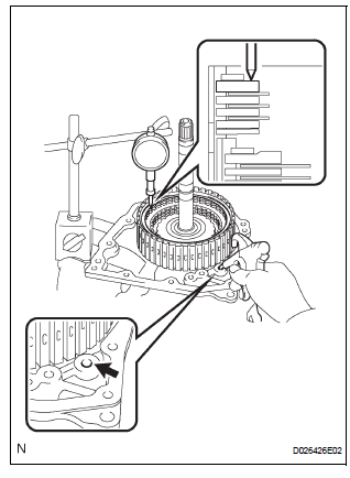
(a) Install the intermediate shaft onto the transaxle rear cover.
(b) Using a dial indicator, measure the direct clutch pack clearance while applying and releasing compressed air (392 kPa, 4.0 kgf/cm2, 57 psi).
Clearance: 0.60 to 0.82 mm (0.02362 to 0.03228 in.)
If the pack clearance is less than the minimum, parts may have been assembled incorrectly, so check and reassemble again. If the clearance is not as specified, select another flange.
HINT: There are 7 flanges of different thickness.
Flange thickness: mm (in.)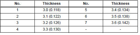
7. INSPECT PACK CLEARANCE OF DIRECT CLUTCH AND OVERDRIVE CLUTCH
(a) Using a dial indicator, measure the direct clutch & overdrive clutch pack clearance while applying and releasing compressed air (392 kPa, 4.0 kgf/cm2, 57 psi).
psi).
Clearance: 0.61 to 0.83 mm (0.02401 to 0.03268 in.)
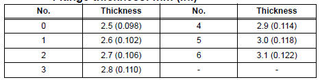
If the pack clearance is less than the minimum, parts may have been assembled incorrectly, so check and reassemble again. If the clearance is not as specified, select another flange.
HINT: There are 7different thicknesses of flanges available
Flange thickness: mm (in.)
(b) Check that the disc rotates when rotating the disc after inserting the rear planetary sun gear.
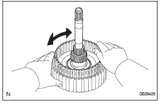
NOTICE: Do not place the rear planetary sun gear in a vise.
 Disassembly
1. INSPECT PACK CLEARANCE OF REVERSE CLUTCH
HINT:
(See page AX-249)
2. INSPECT PACK CLEARANCE OF DIRECT CLUTCH
AND OVERDRIVE CLUTCH
HINT:
(See page AX-249)
3. REMOVE DIRECT MULTIPLE DISC CLUTCH ...
 Reassembly
1. INSTALL OVERDRIVE DIRECT CLUTCH O-RING
(a) Coat an O-ring with ATF, and install it to the direct
clutch drum.
NOTICE:
Make sure that the O-ring is not twisted or
pinched when it is install ...
Other materials:
Removal
1. REMOVE INSTRUMENT PANEL SAFETY PAD SUBASSEMBLY
2. REMOVE ANTENNA CORD SUB-ASSEMBLY
Replace the 5 clamps and remove the antenna cord
sub-assembly.
3. REMOVE PULL TOP ANTENNA POLE SUBASSEMBLY
4. REMOVE ANTENNA ORNAMENT
Remove the antenna ornament.
5. REMOVE ANTENNA ASS ...
Installation
1. INSTALL TRANSFER RH BEARING RETAINER OIL SEAL
(a) Using SST, install a new transfer RH bearing
retainer oil seal to the transfer case at the position
as show in the illustration.
SST 09223-46011
NOTICE:
Do not install the oil seal obliquely
(b) Apply small amount of MP grease to the oi ...
Parking Brake Switch Circuit
DESCRIPTION
This circuit is from the parking brake switch to the radio and navigation
assembly.
WIRING DIAGRAM
INSPECTION PROCEDURE
1 CHECK BRAKE WARNING LIGHT
Check that the brake warning light comes on when the
parking brake is applied and goes off when it is released.
OK:
The ...
