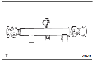
Toyota Sienna Service Manual: Inspection
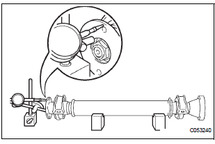
1. INSPECT SPIDER BEARING

(a) Check that the spider bearing moves smoothly by turning the flange.
(b) Check for the looseness around the joint by strongly moving the flange in the axial and radial directions.
HINT: If necessary, replace the shaft.
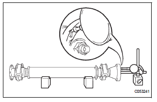
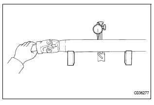
2. INSPECT INTERMEDIATE SHAFT
(a) Using a dial gauge, check for the swing of the intermediate shaft.
Maximum swing: 0.8 mm (0.031 in.)
NOTICE: The dial gauge must be set at right angles to the center of the intermediate shaft.
HINT: If shaft swing exceeds the maximum, replace the shaft.
(b) Using a dial gauge, check for the runout of the front side of the intermediate shaft flange.
Maximum runout: 0.1 mm (0.004 in.)
NOTICE: Ensure that the dial gauge is set at right angles to the measurement surface.
(c) Set a dial gauge outside the bolt hole on the rear side flange of the intermediate shaft, and check for runout in the horizontal direction.
Maximum runout: 0.1 mm (0.004 in.)
NOTICE: Ensure that the dial gauge is set at right angles to the measurement surface.
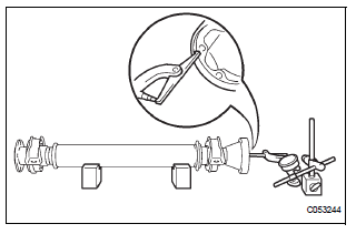
(d) Set a dial gauge to the circumference of the intermediate shaft flange, and check for runout in the vertical direction.
Maximum runout: 0.1 mm (0.004 in.)
NOTICE: Ensure that the dial gauge is set at right angles to the measurement surface.
HINT: If the intermediate shaft flange runout exceeds the maximum, replace the intermediate shaft.
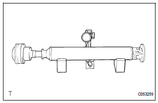
3. INSPECT PROPELLER SHAFT ASSEMBLY
(a) Using a dial gauge, check for the swing of the propeller shaft assembly.
Maximum swing: 0.8 mm (0.031 in.)
HINT: If shaft swing exceeds the maximum, replace the propeller shaft assembly.
NOTICE: The dial gauge must be set at right angles to the center of the propeller shaft.
4. INSPECT CENTER SUPPORT BEARING ASSEMBLY NO.1
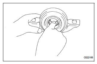
(a) Turn the bearing by hand with applying force in the direction of rotating. Check that the bearing turns smoothly.
(b) Check that the seals and bracket are not cracked or damaged.
HINT: If the bearing is damaged, worn, or does not turn smoothly, replace it.
5. INSPECT CENTER SUPPORT BEARING ASSEMBLY NO.1
(a) Inspect the center support bearing assembly No. 1 (rear) following the same procedures as for the center support bearing assembly No. 1 (front).
6. INSPECT PROPELLER SHAFT ASSEMBLY REAR
(a) Using a dial gauge, check for the runout of the rear propeller shaft assembly rear.
Maximum runout: 0.8 mm (0.031 in.)
HINT: If the shaft runout exceeds the maximum, replace the rear propeller shaft assembly rear.
NOTICE: The dial gauge must be set at right angles to the center of the propeller shaft.
 Disassembly
1. REMOVE PROPELLER SHAFT ASSEMBLY
(a) Put matchmarks on both the flanges.
(b) Remove the 4 nuts, bolts and washers.
2. REMOVE INTERMEDIATE SHAFT
(a) Put matchmarks on the propeller shaf ...
 Reassembly
1. INSTALL CENTER SUPPORT BEARING ASSEMBLY NO.1
(a) Set the center support bearing assembly No. 1
(front) to the intermediate shaft, as shown in the
illustration.
(b) Install a new washer to ...
Other materials:
Center Airbag Sensor Assembly Communication
Circuit Malfunction
DTC B1790 Center Airbag Sensor Assembly Communication
Circuit Malfunction
DESCRIPTION
The center airbag sensor assembly communication circuit consists of the
occupant classification ECU and
the center airbag sensor assembly.
DTC B1790 is recorded when a malfunction is detected in the center ...
Before refueling the vehicle
Close all the doors and windows, and turn the engine switch to the
“LOCK” position (vehicles without a smart key system) or off (vehicles
with a smart key system).
Confirm the type of fuel.
Fuel type
Fuel tank opening for unleaded gasoline
To help prevent incorrect fueling, your ve ...
Ignition Coil Primary / Secondary Circuit
DTC P0351 Ignition Coil "A" Primary / Secondary Circuit
DTC P0352 Ignition Coil "B" Primary / Secondary Circuit
DTC P0353 Ignition Coil "C" Primary / Secondary Circuit
DTC P0354 Ignition Coil "D" Primary / Secondary Circuit
DTC P0355 Ignition Coil "E& ...
