Toyota Sienna Service Manual: Installation
1. INSTALL FRONT AXLE ASSEMBLY LH

(a) Install the 2 bolts, nuts and front axle assembly LH with the 2 bolts and nuts to the shock absorber assembly front LH.
Torque: 230 N*m (2,350 kgf*cm, 170 ft.*lbf)
NOTICE:
- Only when reusing the bolts and nuts, apply the small amount of engine oil to the screw part of the nuts.
- Do not excessively push out the front axle assembly LH.
- Be careful not to damage the outboard joint boot.
- Be careful not to damage the speed sensor rotor.
2. INSTALL FRONT SUSPENSION ARM SUBASSEMBLY LOWER NO.1 LH (See page DS-18)
3. INSTALL TIE ROD END SUB-ASSEMBLY LH (See page DS-18)
4. INSTALL FRONT DISC
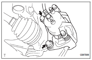
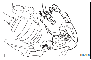
5. INSTALL FRONT DISC BRAKE CALIPER ASSEMBLY LH

(a) Install the front disc brake caliper assembly LH with the 2 bolts to the steering knuckle LH.
Torque: 104 N*m (1,060 kgf*cm, 77 ft.*lbf)
6. INSTALL FRONT AXLE HUB LH NUT
(a) Using a socket wrench (30mm), install a new axle hub LH nut.
Torque: 294 N*m (3,000 kgf*cm, 217 ft.*lbf)
7. SEPARATE FRONT DISC BRAKE CALIPER ASSEMBLY LH
(a) Remove the 2 bolts and separate the front disc brake caliper assembly LH from the steering knuckle LH.
NOTICE: Use a string or other device to keep the brake caliper from hanging down.
8. REMOVE FRONT DISC
9. INSPECT BEARING BACKLASH (See page AH-5)
10. INSPECT AXLE HUB DEVIATION (See page AH-5)
11. INSTALL FRONT DISC
12. INSTALL FRONT DISC BRAKE CALIPER ASSEMBLY LH

(a) Install the front disc brake caliper assembly LH with the 2 bolts to the steering knuckle LH.
Torque: 104 N*m (1,060 kgf*cm, 77 ft.*lbf)
13. INSTALL SPEED SENSOR FRONT LH (See page DS- 18)
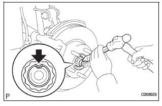
14. INSTALL FRONT AXLE HUB LH NUT

(a) Using a socket wrench (30 mm), install a new axle hub LH nut.
Torque: 294 N*m (3,000 kgf*cm, 217 ft.*lbf) (b) Using a chisel and hammer, stake the axle hub LH nut.
15. INSTALL FRONT WHEEL Torque: 103 N*m (1,050 kgf*cm, 76 ft.*lbf)
16. INSPECT FRONT WHEEL ALIGNMENT
(a) Inspect front wheel alignment (See page SP-4).
17. CHECK ABS SPEED SENSOR SIGNAL
(a) ABS WITH EBD SYSTEM (See page BC-3).
(b) ABS WITH EBD & BA & TRAC & VSC SYSTEM (See page BC-72).
 Reassembly
1. INSTALL FRONT AXLE HUB LH BEARING
(a) Using SST(s) and a press, install a new front axle
hub LH bearing to the steering knuckle LH.
SST 09950-60020 (09951-00810), 09950-70010
(09951-07100 ...
 Rear axle hub bolt
COMPONENTS
Replacement
HINT:
Replace the RH side using the same procedures as for the
LH side.
1. REMOVE REAR WHEEL
2. SEPARATE REAR DISC BRAKE CALIPER
ASSEMBLY LH
(a) Separate rear di ...
Other materials:
Actuator check
1. ACTUATOR CHECK
(a) After entering the DTC check mode (Sensor Check
Mode), press the R/F switch.
(b) As each damper, motor and relay automatically
operate actuator check at 1-second intervals from
step No. 1 to No. 10 continuously, check the
temperature and air flow visually and by hand. ...
Room Temperature Sensor Circuit
DESCRIPTION
This sensor detects the cabin temperature that is used as the basis for
temperature control and sends a
signal to the A/C amplifier.
WIRING DIAGRAM
INSPECTION PROCEDURE
1 READ VALUE OF INTELLIGENT TESTER
(a) Connect the intelligent tester to the DLC3.
(b) Turn the ignition s ...
Reassembly
1. INSTALL 2ND BRAKE PISTON O-RING
(a) Coat 2 new O-rings with ATF, and install them in the
2nd brake piston.
NOTICE:
Make sure that the O-ring is not twisted or
pinched.
2. INSTALL 2ND BRAKE PISTON
(a) Coat the 2nd brake piston with ATF, and install it to
the 2nd brake cylinder.
NO ...
