Toyota Sienna Service Manual: Installation
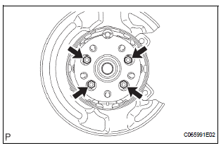
1. INSTALL REAR AXLE HUB & BEARING ASSEMBLY LH

(a) Install the hub & bearing assembly LH with the 4 bolts.
Torque: 56 N*m (571 kgf*cm, 41 ft.*lbf)
2. INSPECT BEARING BACKLASH (See page AH-19)
3. INSPECT AXLE HUB DEVIATION (See page AH-19)
4. INSTALL REAR DRIVE SHAFT ASSEMBLY LH (See page DS-26)
5. INSTALL SPEED SENSOR REAR LH
(a) Install the bolt, connect the speed sensor rear LH.
Torque: 8.0 N*m (82 kgf*cm, 71 in.*lbf)
NOTICE:
- Be careful not to damage the speed sensor.
- Prevent foreign matter from attaching to the speed sensor.
- Do not twist the sensor wire when installing the sensor.
6. INSTALL REAR DISC
7. INSTALL REAR DISC BRAKE CALIPER ASSEMBLY LH
(a) Install the rear disc brake caliper assembly LH with the 2 bolts.
Torque: 88 N*m (900 kgf*cm, 65 ft.*lbf)
8. INSTALL REAR AXLE SHAFT LH NUT (See page DS- 26)
9. INSTALL REAR WHEEL Torque: 103 N*m (1,050 kgf*cm, 76 ft.*lbf)
10. CHECK ABS SPEED SENSOR SIGNAL
(a) ABS WITH EBD & BA & TRAC & VSC SYSTEM (See page BC-72).
 Removal
HINT:
Replace the RH side by the same procedures as the LH side.
1. REMOVE REAR WHEEL
2. REMOVE REAR AXLE SHAFT LH NUT (See page DS-
22)
3. SEPARATE REAR DISC BRAKE CALIPER
ASSEMBLY LH
(a) Remo ...
 Suspension
...
Other materials:
Torque converter clutch and drive plate
Inspection
1. Inspect torque converter clutch assembly
(a) Inspect the one-way clutch.
(1) Set SST into the inner race of the one-way
clutch.
SST 09350-32014 (09351-32010)
(2) Install SST so that it fits in the notch of the
converter hub and outer race of the one-way
clutch.
SST 0 ...
Disassembly
1. INSPECT PACK CLEARANCE OF REVERSE CLUTCH
HINT:
(See page AX-249)
2. INSPECT PACK CLEARANCE OF DIRECT CLUTCH
AND OVERDRIVE CLUTCH
HINT:
(See page AX-249)
3. REMOVE DIRECT MULTIPLE DISC CLUTCH DISC
(a) Using a screwdriver, remove the snap ring from the
intermediate shaft.
(b) Remo ...
Installation
1. INSTALL STEERING PAD
Support the steering pad with one hand as shown in
the illustration.
Connect the 2 connectors to the steering pad.
NOTICE:
When handling the airbag connector, take care
not to damage the airbag wire harness.
Connect the horn connector.
...
