Toyota Sienna Service Manual: Installation
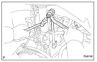
1. INSTALL FRONT SHOCK ABSORBER WITH COIL SPRING
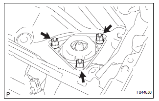
(a) Install the front shock absorber with coil spring as shown in the illustration.
(b) Install the 3 nuts to the upper side of the front shock absorber with coil spring.
Torque: 80 N*m (816 kgf*cm, 59 ft.*lbf)
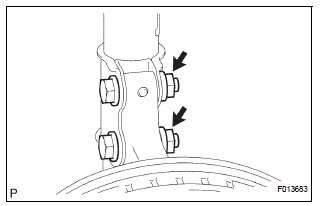
(c) Install the 2 bolts and 2 nuts to the lower side of the front shock absorber with coil spring.
Torque: 210 N*m (2,140 kgf*cm, 155 ft.*lbf)
NOTICE: When installing the bolt, hold the nut not to rotate.
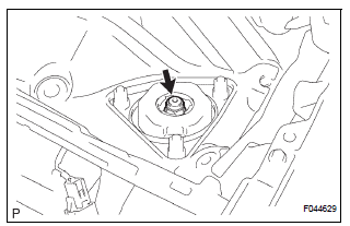
(d) Fully tighten the lock nut.
Torque: 49 N*m (500 kgf*cm, 36 ft.*lbf)
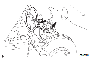
(e) Install the front flexible hose No.1 and speed sensor front LH with the bolt.
Torque: 19 N*m (189 kgf*cm, 14 ft.*lbf)
2. INSTALL FRONT STABILIZER LINK ASSEMBLY LH
(a) Install the front stabilizer link assembly LH with the nut.
Torque: 74 N*m (755 kgf*cm, 55 ft.*lbf)
HINT: If the ball joint turns together with the nut, use a hexagon (6 mm) wrench to hold the stud.
3. INSTALL COWL TOP PANEL SUB-ASSEMBLY OUTER FRONT
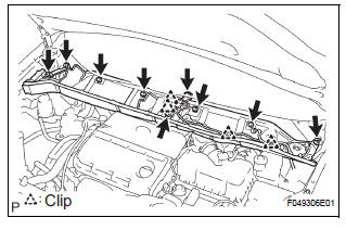
(a) Install the cowl top brace and cowl top panel subassembly outer front with the 9 bolts.
Torque: 7.5 N*m (76 kgf*cm, 66 in.*lbf) (b) Connect the wire harness to the cowl top panel subassembly outer front.
4. INSTALL WINDSHIELD WIPER MOTOR & LINK ASSEMBLY
HINT: (See page WW-3)
5. INSTALL FR WIPER ARM LH
HINT: (See page WW-3)
6. INSTALL FR WIPER ARM RH
HINT: (See page WW-3)
7. INSTALL FRONT WHEEL Torque: 103 N*m (1,050 kgf*cm, 76 ft.*lbf)
8. INSPECT AND ADJUST FRONT WHEEL ALIGNMENT
HINT: (See page SP-4)
 Reassembly
1. INSTALL SHOCK ABSORBER ASSEMBLY FRONT LH
2. INSTALL FRONT COIL SPRING INSULATOR LOWER
LH
(a) Install the front coil spring insulator lower LH onto
the shock absorber assembly front LH.
3. INST ...
 Disposal
1. DISPOSE OF SHOCK ABSORBER ASSEMBLY FRONT LH
HINT:
Dispose the RH side by the same procedures as the LH
side.
(a) Fully extend the shock absorber rod.
(b) Using a drill, make a hole in the cy ...
Other materials:
Rear wiper rubber
COMPONENTS
REMOVAL
1. REMOVE REAR WIPER BLADE ASSEMBLY
Remove the rear wiper arm head cap from the rear
wiper arm.
Raise the rear wiper blade to the position as shown
in the illustration where the meshing of the claw is
disengaged with the click sound.
NOTICE:
...
Manual Up / Down Function does not Operate on Rear RH Only
DESCRIPTION
If the manual UP/DOWN function does not operate, the power window motor, the
regulator switch or the
wire harness may be malfunctioning.
WIRING DIAGRAM
INSPECTION PROCEDURE
1 CHECK WIRE HARNESS (POWER SOURCE)
Disconnect the P39 regulator switch connector.
Turn ...
Cleaning and protecting
the vehicle interior
The following procedures will help protect your vehicle’s interior
and keep it in top condition:
Protecting the vehicle interior
Remove dirt and dust using a vacuum cleaner. Wipe dirty surfaces
with a cloth dampened with lukewarm water.
Cleaning the leather areas
Remove dirt and dust usin ...
