Toyota Sienna Service Manual: Installation
1. INSTALL SHOCK ABSORBER ASSEMBLY REAR LH
(a) Install the rear spring bumper No.1 LH to the shock absorber assembly LH.
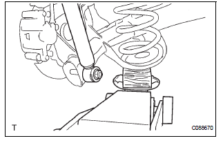
(b) Support the rear axle beam assembly with a jack.
(c) Install the rear shock absorber assembly rear LH, cushion retainer and nut to the rear axle beam.
(d) Install the rear shock absorber cushion No.1 and rear shock absorber LH cushion retainer.
(e) Temporary tighten a new lock nut.
(f) Using a 6mm hexagon wrench to hold the piston rod, fully tighten the lock nut.
Torque: 30 N*m (310 kgf*cm, 22 ft.*lbf)
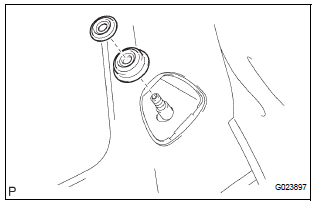
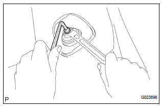
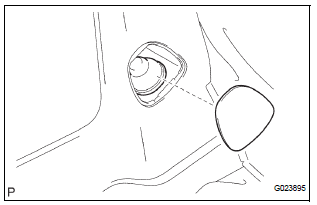
2. INSTALL REAR SHOCK ABSORBER CAP LH
(a) Install the shock absorber cap LH as shown in the illustration.
(b) Install the shock absorber head cover.
3. INSTALL REAR WHEEL
Torque: 103 N*m (1,050 kgf*cm, 76 ft.*lbf)
4. FULLY TIGHTEN SHOCK ABSORBER ASSEMBLY REAR LH
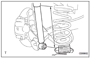
(a) Stabilize the shock absorber assembly rear LH.
If it is impossible to tighten the nut at this position, support the rear axle beam with a jack and load the rear compartment with a mass of approximately 90 kg (198 lb).
Length of shock absorber: 2WD DRIVE TYPE: 234 mm (9.22 in.) 4WD DRIVE TYPE: 258 mm (10.16 in.)
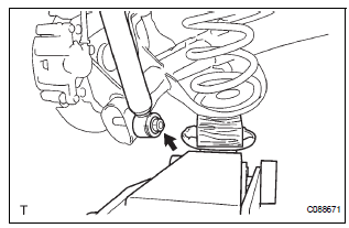
(b) Fully tighten the nut.
Torque: 115 N*m (1,173 kgf*cm, 85 ft.*lbf)
5. INSPECT REAR WHEEL ALIGNMENT
HINT: (See page SP-9)
 Inspection
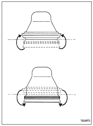
1. INSPECT SHOCK ABSORBER ASSEMBLY REAR LH
(a) Push down and pull up the shock absorber rod, and
check that there is no unusual resistance or unusual
operation sound.
If there is any malfunc ...
 Disposal
1. DISPOSE OF SHOCK ABSORBER ASSEMBLY REAR LH
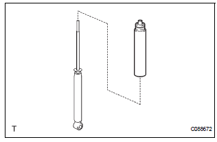
(a) Fully extend the shock absorber rod.
(b) Using a drill, make a hole in the cylinder as shown in
the illustration to discharge the gas inside ...
Other materials:
A/C ECU Communication Stop
DTC B1262 A/C ECU Communication Stop
DESCRIPTION
DTC B1262 is output when communication between the A/C amplifier and the
multiplex network gateway
ECU stops for more than 10 seconds.
DTC No.
DTC Detection Condition
Trouble Area
B1262
A/C ECU communicat ...
Initialization
1. ZERO POINT CALIBRATION
NOTICE:
Make sure that the front passenger seat is not
occupied before performing the operation.
HINT:
Perform the zero point calibration and sensitivity check if
any of the following conditions occur.
The occupant classification ECU is replaced.
Acc ...
Fail-safe chart
HINT:
If the following conditions are detected while the cruise
control is in operation, the system clears the stored vehicle
speed in the ECM and cancels the cruise control operation.
Vehicle Condition
Auto Cancel Condition
Re-operation Condition
CRUISE main in ...
