Toyota Sienna Service Manual: Installation
1. INSTALL TIRE PRESSURE WARNING VALVE AND TRANSMITTER
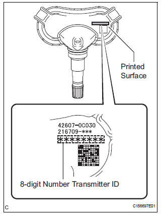
(a) Insert the tire pressure warning valve and transmitter into the valve installation hole. Insert it from the inside of the rim so that the printed surface can be seen.
NOTICE:
- Check that there is no visible deformation, damage, or other abnormalities on the tire pressure warning valve and transmitter.
- Check that there is no foreign matter on the inner grommet and around the rim hole.
- If the tire pressure warning valve and transmitter is installed upside down, it may be damaged or fail to transmit signals when running at high speeds.
- If installing a new tire pressure warning valve and transmitter, write down the ID number before installation.
- It is necessary to register the ID in the ECU after installation (See page TW-20).
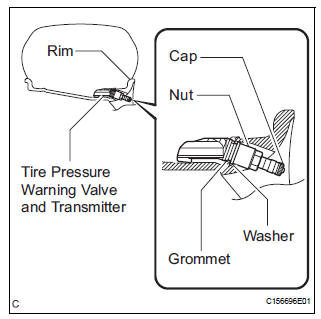
(b) Install the washer on the tire pressure warning valve and transmitter from the rim side and tighten the nut.
Torque: 4.0 N*m (41 kgf*cm, 35 in.*lbf)
NOTICE:
- No further tightening is required once the nut is tightened to the specified torque.
- Check that there is no foreign matter on the washer and nut.
- If replacing the tire pressure warning valve and transmitter, make sure that the new grommet, washer, and nut are used.
- Check that there is no oil, water, or lubricant
around the rim hole, tire pressure warning
valve and transmitter, washer, and nut.
Failing to do so may result in improper installation.
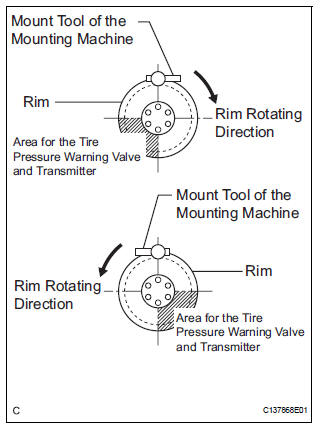
(c) Set the wheel disc to the mounting machine and install the lower tire bead. Position the main body of the tire pressure warning valve and transmitter in the shaded area shown in the illustration.
NOTICE:
- If the tire pressure warning valve and transmitter is positioned outside this area, it will be interfered with the tire bead, and may cause damage to the tire pressure warning valve and transmitter.
- If the use of lubricant is required when installing the bead, do not apply the lubricant directly to the tire pressure warning valve and transmitter.
(d) Install the upper bead.
NOTICE: Make sure that the tire bead and tool do not interfere with the main body of the tire pressure warning valve and transmitter and that it is not clamped by the bead.
(e) After the tire is inflated, the valve nut may be loose.
Retighten the nut to the specified torque and then check for air leaks with soapy water.
Torque: 4.0 N*m (41 kgf*cm, 35 in.*lbf)
NOTICE: No further tightening is required once the nut is tightened to the specified torque.
2. INSTALL FRONT WHEEL Torque: 103 N*m (1050 kgf*cm, 76 ft.*lbf)
3. INSTALL REAR WHEEL Torque: 103 N*m (1050 kgf*cm, 76 ft.*lbf)
4. INSPECT TIRES
HINT: See page TW-2.
5. REGISTER TRANSMITTER ID
HINT: See page TW-20.
6. INSPECT TIRE PRESSURE WARNING SYSTEM
HINT: See page TW-25.
 Removal
1. REMOVE FRONT WHEEL
2. REMOVE REAR WHEEL
3. REMOVE TIRE PRESSURE WARNING VALVE AND TRANSMITTER
(a) Remove the valve core and cap, and release the air
from the tire.
(b) After ensuring tha ...
 Disposal
HINT:
The tire pressure warning valve and transmitter is powered
by a lithium battery. When disposing of the tire pressure
warning valve and transmitter, remove the battery and
dispose of it corre ...
Other materials:
Installation
1. INSTALL TRANSAXLE HOUSING OIL SEAL
(a) Using SST and a hammer, install a new oil seal.
SST 09316-60011 (09316-00011)
Oil seal installation depth:
-0.5 to 0.5 mm (-0.020 to 0.020 in.)
(b) Coat the lip of the oil seal with MP grease.
2. INSTALL DIFFERENTIAL SIDE BEARING RETAINER OIL SEA ...
Safety Connect LED light Indicators
When the engine switch is turned to the “ON” position (vehicles without
a smart key system) or IGNITION ON mode (vehicles with a smart
key system), the red indicator light comes on for 2 seconds then turns
off. Afterward, the green indicator light comes on, indicating that the
service is act ...
Back-up light assembly
COMPONENTS
REMOVAL
1. REMOVE BACK DOOR GARNISH CENTER
2. REMOVE BACK DOOR SIDE GARNISH LH
3. REMOVE BACK DOOR SIDE GARNISH RH
4. REMOVE BACK DOOR STRAP COVER SUBASSEMBLY
5. REMOVE BACK DOOR PULL STRAP
6. REMOVE BACK DOOR TRIM BOARD ASSEMBLY
7. REMOVE BACK-UP LIGHT ASSEMBLY
&n ...
