Toyota Sienna Service Manual: Installation
1. INSTALL TIRE PRESSURE WARNING ECU
(a) Connect the connector to the tire pressure warning ECU.
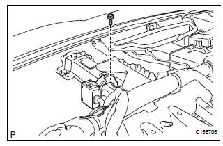
(b) Install the tire pressure warning ECU with the screw.
2. INSTALL INSTRUMENT PANEL SAFETY PAD SUBASSEMBLY
HINT: Refer to the instructions for INSTALLATION of the instrument panel safety pad (See page IP-14)
3. CONNECT CABLE TO BATTERY NEGATIVE TERMINAL
4. REGISTER TRANSMITTER ID
HINT: See page TW-20.
5. INSPECT TIRE PRESSURE WARNING SYSTEM
HINT: See page TW-25.
6. INITIALIZE SYSTEM
NOTICE:
- Be sure to register the transmitter IDs of all tires in the ECU before initialization.
- Be sure to inflate all tires to the proper inflation pressure before initialization.
HINT: See page TW-23.
 Removal
NOTICE:
Before removing the tire pressure warning ECU, read the
registered transmitter IDs of all wheels and write them
down to use for re-registration of transmitter IDs (See
page TW-20).
1. DIS ...
 Tire pressure warning reset switch
COMPONENTS
...
Other materials:
Fail-safe chart
1. FAIL-SAFE
This function minimizes the loss of the ECT functions
when any malfunction occurs in a sensor or solenoid.
(a) ATF (Automatic Transmission Fluid) temperature
sensor:
When the ATF temperature sensor has a
malfunction, 5th upshift is prohibited.
(b) Counter gear speed sensor NC ...
Evaporative Emission System Reference Orifice
DTC SUMMARY
HINT:
The 0.02 inch orifice is located inside the pump module.
DESCRIPTION
The circuit description can be found in the EVAP (Evaporative Emission)
System (See page ES-409).
INSPECTION PROCEDURE
Refer to the EVAP System (See page ES-412).
MONITOR DESCRIPTION
5 hours*1 af ...
Disassembly
1. SEPARATE REAR DRIVE SHAFT INBOARD JOINT BOOT CLAMP
(a) Using a screwdriver, remove the 2 rear drive shaft
inboard joint boot clamps as shown in the
illustration.
2. SEPARATE REAR DRIVE SHAFT INBOARD JOINT
BOOT
(a) Separate the rear drive shaft inboard joint boot from
the inboard joint ...
