Toyota Sienna Service Manual: Installation
HINT: Install the RH side by the same procedures with LH side.
1. INSTALL FRONT SPEED SENSOR LH
(a) Install the speed sensor front LH with the bolt.
Torque: 8.0 N*m (82 kgf*cm, 71 in.*lbf)
NOTICE: Keep the tip of the front speed sensor LH.
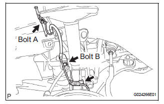
(b) Install the sensor harness clamps with the 2 bolts A and B to the body and shock absorber.
Torque: Bolt A 8.0 N*m (82 kgf*cm, 71 in.*lbf)
Bolt B 19 N*m (192 kgf*cm, 14 ft.*lbf)
NOTICE: Do not twist the sensor wire when installing the sensor.
(c) Connect the clamp to the knuckle.
(d) Install the sensor harness and clamp to the body.
(e) Connect the speed sensor connector.
2. INSTALL FRONT FENDER LINER LH
3. REMOVE FRONT WHEEL Torque: 103 N*m (1,050 kgf*cm, 76 ft.*lbf)
4. CHECK ABS SPEED SENSOR SIGNAL
HINT: See page BC-3
 Inspection
1. INSPECT FRONT SPEED SENSOR
(a) Make sure that there is no looseness at the
connector lock part and connecting part of the
connector.
(b) Disconnect the speed sensor connector.
(c) Measure ...
 Rear speed sensor (for 2wd)
Components
...
Other materials:
Cold Start Ignition Timing Performance
DESCRIPTION
This monitor will run when the engine is started at -10 to 50°C (14 to 122°F)
of the engine coolant
temperature. The DTC will set after the engine idling for 13 seconds (2 trip
detection logic).
The DTC is designed to monitor the idle air control at cold start. When the
...
Registration
NOTICE:
The Vehicle Identification Number (VIN) must be input
into the replacement ECM.
HINT:
The VIN is a 17-digit alphanumeric vehicle identification
number. The intelligent tester is required to register the VIN.
1. INPUT INSTRUCTIONS
The general VIN input instructions using the
...
Map Disc Read Error
DTC 58-42 Map Disc Read Error
DTC 80-42 Map Disc Read Error
DESCRIPTION
DTC No.
DTC Detection Condition
Trouble Area
58-42
Player error
Scratches or dirt on the disc
Access to an invalid address due to software error
...
