Toyota Sienna Service Manual: Installation
1. INSTALL BRAKE ACTUATOR
(a) Install the brake actuator assembly with the 2 nuts.
Torque: 5.4 N*m (55 kgf*cm, 48 in.*lbf)
2. INSTALL BRAKE ACTUATOR WITH BRACKET
(a) Install the actuator with bracket with the 3 bolts.
Torque: 20 N*m (199 kgf*cm, 14 ft.*lbf)
NOTICE: Be careful not to damage the brake tubes and wire harness.
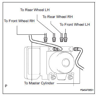
(b) Using SST, connect each brake tube to correct positions of the actuator with bracket, as shown in the illustration.
Torque: 15 N*m (155 kgf*cm, 11 ft.*lbf)
(c) Connect the brake actuator connector assembly.
3. INSTALL AIR CLEANER ASSEMBLY WITH HOSE
4. FILL RESERVOIR WITH BRAKE FLUID (See page BR- 3)
5. BLEED BRAKE MASTER CYLINDER SUBASSEMBLY (See page BR-3)
6. BLEED BRAKE LINE (See page BR-4)
7. CHECK BRAKE FLUID LEAKAGE
8. CHECK FLUID LEVEL IN RESERVOIR (See page BR- 7)
9. CONNECT BATTERY NEGATIVE TERMINAL
10. PERFORM INITIALIZATION
11. CHECK BRAKE ACTUATOR WITH INTELLIGENT TESTER
HINT: See page BC-183.
 Removal
1. DRAIN BRAKE FLUID
NOTICE:
Wash brake fluid off immediately if it adheres to any
painted surface.
2. DISCONNECT BATTERY NEGATIVE TERMINAL
3. REMOVE AIR CLEANER ASSEMBLY WITH HOSE
4. REMOVE BRA ...
Other materials:
Rear evaporator temperature sensor circuit
DESCRIPTION
The rear evaporator temperature sensor is installed on the rear evaporator.
It detects the rear evaporator
temperature. The sensor sends a signal to the A/C amplifier. The resistance of
the rear evaporator
temperature sensor changes in accordance with the rear evaporator temperatu ...
VSC Warning Light does not Come ON
DESCRIPTION
The skid control ECU is connected to the combination meter via CAN and
multiplex communications.
If the skid control ECU stores DTCs to shut down TRAC and VSC operation, the VSC
warning light comes
on in the combination meter.
WIRING DIAGRAM
Refer to VSC Warning Light Remains ...
Internal Control Module Random Access Memory
(RAM) Error
DTC P0604 Internal Control Module Random Access Memory
(RAM) Error
DESCRIPTION
The ECM continuously monitors its own internal memory status, internal
circuits, and output signals
transmitted to the throttle actuator. This self-check ensures that the ECM is
functioning properly. If any
malfu ...
