Toyota Sienna Service Manual: Installation
1. INSTALL BRAKE PEDAL SUPPORT ASSEMBLY

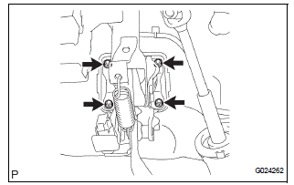
(a) Install the brake pedal support sub-assembly with the 4 nuts.
Torque: 16 N*m (160 kgf*cm, 12 ft.*lbf) (b) Install the clip and clevis pin to the brake pedal lever.
(c) Using needle-nose pliers, install the tension spring.

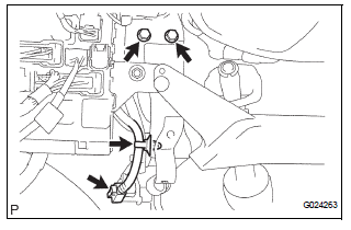
(d) Install the 2 bolts to the brake pedal bracket No. 3.
Torque: 19 N*m (194 kgf*cm, 14 ft.*lbf) (e) Install the stop light switch harness clamp to the brake pedal support sub-assembly.
(f) Connect the stop light switch connector.
2. FULLY TIGHTEN BRAKE PEDAL SHAFT

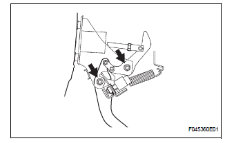
(a) Fully tighten the 2 brake pedal shafts.
Torque: 34 N*m (350 kgf*cm, 25 ft.*lbf)
3. INSTALL INSTRUMENT PANEL SAFETY PAD INSERT SUB-ASSEMBLY NO. 1
(a) Install the instrument panel safety pad insert subassembly No. 1 with the 4 bolts.
4. INSTALL INSTRUMENT PANEL FINISH PANEL SUBASSEMBLY LOWER LH
(a) Install the instrument panel finish panel subassembly lower LH with the 2 bolts.
5. INSTALL COWL SIDE TRIM BOARD LH
6. INSTALL FRONT DOOR SCUFF PLATE LH
7. INSPECT BRAKE PEDAL HEIGHT (See page BR-9)
8. CHECK PEDAL FREE PLAY (See page BR-10)
9. CHECK PEDAL RESERVE DISTANCE (See page BR- 10)
 Reassembly
1. INSTALL BRAKE PEDAL PAD
(a) Install the brake pedal pad to the brake pedal subassembly.
2. INSTALL PUSH ROD PIN
(a) Apply lithium soap base glycol grease to inside
surface of 2 new push rod bus ...
 Brake master cylinder
COMPONENTS
...
Other materials:
System description
1. OUTLINE OF THEFT DETERRENT SYSTEM
When the theft deterrent system detects that the
vehicle is being tampered with, the system sets off
the alarm, causing the horns to sound and the lights
to light up or blink in order to alert people around the
vehicle to the theft.
The ...
Air Mix Damper Position Sensor Circuit (Passenger Side)
DESCRIPTION
This sensor detects the position of the air mix control servo motor (air mix
damper) and sends the
appropriate signals to the A/C amplifier. The position sensor is built in the
air mix control servo motor. The
position sensor's resistance changes as the air mix control servo m ...
Customizable features
Settings that can be changed using the audio system screen
Settings that can be changed using the multi-information display
Settings that can be changed by your Toyota dealer
Definition of symbols: O = Available, – = Not available
Gauges, meters and multi-information display (, 93)
...
