Toyota Sienna Service Manual: Installation
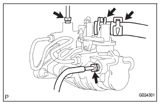
1. INSTALL BRAKE MASTER CYLINDER

(a) Install the brake master cylinder with the 2 nuts.
Torque: 13 N*m (130 kgf*cm, 9 ft.*lbf) (b) Slide the clip and connect the brake master cylinder reservoir hose.

(c) Using SST, connect the 2 brake tube to the brake master cylinder.
SST 09023-00101 Torque: 15 N*m (155 kgf*cm, 11 ft.*lbf)
2. INSTALL AIR CLEANER ASSEMBLY WITH HOSE
3. FILL RESERVOIR WITH BRAKE FLUID (See page BR- 3)
4. BLEED BRAKE MASTER CYLINDER (See page BR-3)
5. BLEED BRAKE LINE (See page BR-4)
6. BLEED BRAKE ACTUATOR (w/ VSC) (See page BR- 4)
7. CHECK BRAKE FLUID LEVEL IN RESERVOIR (See page BR-7)
8. CHECK BRAKE FLUID LEAKAGE
9. INSTALL COWL TOP PANEL SUB-ASSEMBLY OUTER FRONT
10. INSPECT BRAKE PEDAL HEIGHT (See page BR-9)
11. CHECK BRAKE ACTUATOR WITH INTELLIGENT
TESTER 
 Reassembly
1. INSTALL BRAKE MASTER LESS RESERVOIR TANK CYLINDER SUB-ASSEMBLY
(a) Apply lithium soap base glycol grease to the 2 brake
master cylinder union grommets and install them to
the brake master less r ...
 Brake booster
COMPONENTS
...
Other materials:
Calibrating the compass
The direction display deviates from the true direction determined by
the earth’s magnetic field. The amount of deviation varies according to
the geographic position of the vehicle.
If you cross over a map boundary shown in illustration, the compass will
deviate.
To obtain higher preci ...
On-vehicle inspection
1. INSPECT REAR AXLE HUB BEARING BACKLASH
(a) Using a dial gauge, check for backlash near the
center of the axle hub.
Maximum:
0.05 mm (0.0020 in.)
If backlash exceeds the maximum, replace the axle
hub assembly.
NOTICE:
Ensure that the dial gauge is set at right angles
to the measuremen ...
Disassembly
1. REMOVE COOLER DRYER
(a) Using a hexagon wrench 14 mm (0.55 in.), remove
the cap from the modulator.
(b) Remove the O-ring from the cap.
(c) Using needle nose pliers, remove the cooler dryer. ...
