Toyota Sienna Service Manual: Installation
1. INSTALL BRAKE VACUUM CHECK VALVE ASSEMBLY
(a) Install the brake vacuum check valve assembly and check valve grommet to the brake booster assembly.
2. INSTALL BRAKE BOOSTER GASKET
(a) Install a new brake booster gasket to the brake booster with master cylinder.
3. INSTALL BRAKE MASTER CYLINDER ASSEMBLY
(a) Install the brake booster assembly with the 4 nuts.
Torque: 13 N*m (130 kgf*cm, 9 ft.*lbf) (b) Slide the clip and connect the brake master cylinder reservoir hose to the brake master cylinder union.
(c) Slide the clip and connect the vacuum hose from the brake vacuum check valve assembly.
4. INSTALL PUSH ROD PIN
(a) Install the push rod pin to the brake booster push rod.
5. INSTALL BRAKE LINE
(a) Install the front brake tube No. 1, front brake tube No. 2, front brake tube No. 3 and front brake tube No. 4.
Torque: 15 N*m (155 kgf*cm, 11 ft.*lbf) (b) Install the rear brake tube No. 1and rear brake tube No. 2.
Torque: 15 N*m (155 kgf*cm, 11 ft.*lbf)
6. INSTALL BRAKE ACTUATOR ASSEMBLY (w/o VSC) SST 09023-00101
HINT: See page BC-184
7. INSTALL ABS & TRACTION ACTUATOR ASSEMBLY (w/ VSC) SST 09023-00101
HINT: See page BC-179.
8. INSTALL AIR CLEANER ASSEMBLY WITH HOSE
9. FILL RESERVOIR WITH BRAKE FLUID (See page BR- 3)
10. BLEED BRAKE MASTER CYLINDER (See page BR-3)
11. BLEED BRAKE LINE (See page BR-4)
12. BLEED BRAKE ACTUATOR (w/ VSC) (See page BR- 4)
13. CHECK FLUID LEVEL IN RESERVOIR (See page BR- 7)
14. CHECK BRAKE FLUID LEAKAGE
15. INSTALL INSTRUMENT PANEL SAFETY PAD INSERT SUB-ASSEMBLY NO. 1
(a) Install the instrument panel safety pad insert subassembly No. 1 with the 4 bolts.
16. INSTALL INSTRUMENT PANEL FINISH PANEL SUBASSEMBLY LOWER LH
(a) Install the instrument panel finish panel subassembly lower LH with the 2 bolts.
17. INSTALL COWL SIDE TRIM BOARD LH
(a) Install the cowl trim board plate LH with the nut.
18. INSTALL FRONT DOOR SCUFF PLATE LH
19. INSTALL COWL TOP PANEL SUB-ASSEMBLY OUTER FRONT
20. INSTALL FRONT WHEEL Torque: 103 N*m (1,050 kgf*cm, 76 ft.*lbf)
21. INSPECT BRAKE PEDAL HEIGHT (See page BR-9)
22. CHECK BRAKE ACTUATOR WITH INTELLIGENT
TESTER 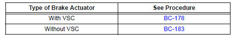
 Inspection
1. INSPECT BRAKE VACUUM CHECK VALVE ASSEMBLY
(a) Check the vacuum check valve.
(1) Slide the clip and disconnect the vacuum hose.
(2) Remove the vacuum check valve.
(3) Check that there ...
 Front brake
COMPONENTS
...
Other materials:
Internal Control Module Random Access Memory
(RAM) Error
DTC P0604 Internal Control Module Random Access Memory
(RAM) Error
DESCRIPTION
The ECM continuously monitors its own internal memory status, internal
circuits, and output signals
transmitted to the throttle actuator. This self-check ensures that the ECM is
functioning properly. If any
malfu ...
Repair
1. REPAIR REAR WINDOW DEFOGGER WIRE
Clean the broken wire tips with grease, wax and
silicone remover.
Place the masking tape along the both sides of the
wire.
Thoroughly mix the repair agent (Dupont paste No.
4817).
Using a fine tip brush, apply a smal ...
Power outlets
The power outlet can be used for the following components:
12 V: Accessories that run on less than 10 A
120 V AC: Accessories that use less than 100 W
12 V
Open the cover.
Center panel type A
Center panel type B
Luggage compartment
120 V AC (if equipped)
Open the ...
