Toyota Sienna Service Manual: Installation
1. INSTALL RACK & PINION POWER STEERING GEAR ASSEMBLY
(a) Install the power steering gear assembly with the 2 bolts and nuts.
Torque: 70 N*m (714 kgf*cm, 52 ft.*lbf)
2. CONNECT PRESSURE FEED TUBE ASSEMBLY
(a) Connect the pressure feed tube assembly to the power steering gear assembly.
(b) Install the clip.
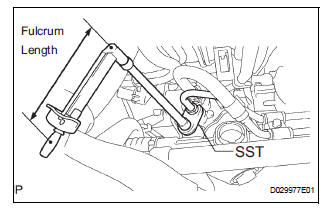
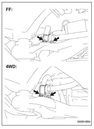
(c) Using SST, connect the return tube assembly to the power steering gear assembly.
SST 09023-12701 Torque: 22.5 N*m (229 kgf*cm, 17 ft.*lbf)
HINT
- Use a torque wrench with a fulcrum length of 300 mm (11.81 in.).
- This torque value is effective when SST is parallel to the torque wrench.
(d) Install the tube clamp with the bolt.
Torque: 9.8 N*m (100 kgf*cm, 87 in.*lbf)
(e) Install the tube clamp with the nut.
Torque: 9.8 N*m (100 kgf*cm, 87 in.*lbf)
3. INSTALL FRONT STABILIZER BRACKET NO.1 LH
(a) Install the stabilizer bracket No. 1 with the 2 bolts.
Torque: 17 N*m (173 kgf*cm, 12 ft.*lbf)
4. INSTALL FRONT STABILIZER BRACKET NO.1 RH
HINT: Perform the same procedure on the other side.
5. INSTALL FRONT STABILIZER LINK ASSEMBLY LH
6. INSTALL FRONT STABILIZER LINK ASSEMBLY RH
HINT: Perform the same procedure on the other side.
7. INSTALL STEERING INTERMEDIATE SHAFT ASSEMBLY
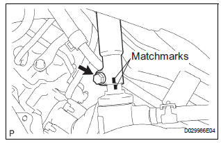
(a) Align matchmarks on the intermediate shaft assembly and power steering gear assembly.
(b) Install the bolt.
Torque: 36 N*m (367 kgf*cm, 27 ft.*lbf)
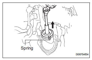
(c) Install the dust cover.
HINT: Ensure that the springs are installed tightly.
8. INSTALL TIE ROD ASSEMBLY LH
9. INSTALL TIE ROD ASSEMBLY RH
HINT: Perform the same procedure on the other side.
10. INSTALL FRONT WHEEL Torque: 103 N*m (1,050 kgf*cm, 76 ft.*lbf)
11. INSPECT CENTER FRONT WHEEL
12. INSPECT STEERING WHEEL CENTER POINT
13. ADD POWER STEERING FLUID
14. BLEED POWER STEERING FLUID
HINT: (See page PS-6)
15. INSPECT FOR POWER STEERING FLUID LEAK
16. INSPECT AND ADJUST FRONT WHEEL ALIGNMENT
HINT: (See page SP-4)
 Reassembly
1. INSTALL RACK STEERING PISTON RING
(a) Coat a new O-ring with power steering fluid and
install it onto the power steering rack.
(b) Expand a new rack steering piston ring with your
fingers ...
 Air conditioning
...
Other materials:
DTC check / clear
1. CHECK DTC
Connect the intelligent tester to the Controller Area
Network Vehicle Interface Module (CAN VIM). Then
connect the CAN VIM to the DLC3.
Turn the ignition switch on.
Turn the tester ON.
Enter the following menu items: DIAGNOSIS / OBD/
MOBD / IM ...
How to use this manual
GENERAL INFORMATION
1. GENERAL DESCRIPTION
(a) This manual is written in accordance with SAE J2008.
(b) Repair operations can be separated mainly in the following 3 processes:
(1) Diagnosis
(2) Removing / Install ...
Engine Coolant Temperature Circuit
DTC P0115 Engine Coolant Temperature Circuit
DTC P0117 Engine Coolant Temperature Circuit Low Input
DTC P0118 Engine Coolant Temperature Circuit High Input
DESCRIPTION
A thermistor is built into the Engine Coolant Temperature (ECT) sensor, of
which the resistance value
varies according to the ...
