Toyota Sienna Service Manual: Installation
1. TEMPORARILY TIGHTEN AIR CONDITIONING UNIT ASSEMBLY
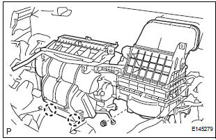
(a) Engage the 2 claws.
(b) Temporarily tighten the air conditioning unit assembly with the nut.
Torque: 9.8 N*m (100 kgf*cm, 87 in.*lbf)
2. INSTALL LOWER DEFROSTER NOZZLE ASSEMBLY
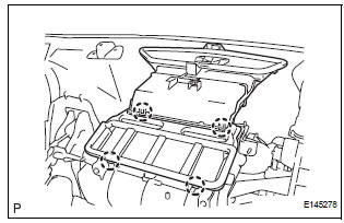
(a) Engage the 4 claws and install the lower defroster nozzle assembly.
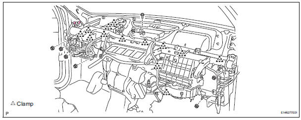
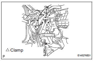
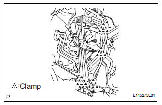
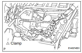
3. INSTALL INSTRUMENT PANEL REINFORCEMENT
(a) Install the instrument panel reinforcement with the 10 bolts.
(b) Install the 13 clamps.
(c) Connect the connectors.
(d) Install the screw.
(e) Install the 6 nuts.
Torque: 7.3 N*m (74 kgf*cm, 65 in.*lbf)
4. INSTALL AIR CONDITIONING UNIT ASSEMBLY
(a) Install the air conditioner unit assembly with the 3 bolts and 2 nuts.
Torque: 9.8 N*m (100 kgf*cm, 87 in.*lbf)
5. INSTALL FRONT FENDER GARNISH RH
6. INSTALL ECM (See page ES-499)
7. INSTALL STEREO COMPONENT AMPLIFIER ASSEMBLY (w/ Stereo Component Amplifier) (See page AV-173)
8. INSTALL NO. 2 INSTRUMENT PANEL BRACE SUBASSEMBLY
(a) Install the No. 2 instrument panel brace subassembly with the 3 bolts and 2 nuts.
(b) Engage the 2 clamps.
(c) Connect the connector.
9. INSTALL NO. 1 INSTRUMENT PANEL BRACE SUBASSEMBLY
(a) Install the No. 1 instrument panel brace subassembly with the 3 bolts and 2 nuts.
(b) Engage the 4 clamps.
(c) Install the bolt.
(d) Connect the connector.
10. INSTALL NO. 5 INSTRUMENT PANEL BRACKET
(a) Install the No. 5 instrument panel bracket with the 4 nuts.
(b) Engage the 2 clamps.
(c) Connect the connector.
11. INSTALL SHIFT LEVER ASSEMBLY
HINT: (See page AX-150 for U151E, AX-150 for U151F)
12. CONNECT TRANSMISSION CONTROL CABLE ASSEMBLY
HINT: (See page AX-156 for U151E, AX-156 for U151F)
13. INSTALL STEERING COLUMN ASSEMBLY (See page SR-10)
14. CONNECT STEERING INTERMEDIATE SHAFT ASSEMBLY (See page SR-10)
15. INSTALL NO. 1 HEATER TO FOOT DUCT
(a) Install the No. 1 heater to foot duct with the clip.
16. INSTALL NO. 3 HEATER TO FOOT DUCT
(a) Install the No. 3 heater to foot duct with the clip.
17. INSTALL SPIRAL CABLE (See page RS-434)
18. INSTALL INSTRUMENT PANEL ASSEMBLY WITH PASSENGER AIRBAG ASSEMBLY
HINT: (See page IP-14)
19. INSTALL HEATER WATER INLET HOSE A
20. CONNECT HEATER WATER OUTLET HOSE A (FROM HEATER UNIT)
(a) Using pliers, grip the claws of the clip and slide the clip to connect the heater water outlet hose A (from heater unit).
21. INSTALL AIR CLEANER CAP SUB-ASSEMBLY (See page IT-5)
22. INSTALL SUCTION HOSE SUB-ASSEMBLY
(a) Lubricate a new O-ring with compressor oil and install it on the hose.
Compressor oil: ND-OIL 8 or equivalent
(b) Install the suction hose sub-assembly and the piping clamp.
HINT: After the connection, check the claw fitting of the piping clamp.
23. INSTALL COOLER REFRIGERANT LIQUID PIPE E (TO COOLER UNIT)
(a) Lubricate a new O-ring with compressor oil and install it to the pipe.
Compressor oil: ND-OIL 8 or equivalent
(b) Install the cooler refrigerant liquid pipe E and the piping clamp.
HINT: After the connection, check the claw fitting of the piping clamp.
24. INSTALL FRONT COWL TOP OUTER PANEL SUBASSEMBLY (See page SP-18)
25. INSTALL WINDSHIELD WIPER MOTOR AND LINK ASSEMBLY (See page WW-6)
26. INSTALL COWL TOP VENTILATOR LOUVER SUBASSEMBLY (See page WW-6)
27. INSTALL FRONT WIPER ARM LH (See page WW-6)
28. INSTALL FRONT WIPER ARM RH (See page WW-7)
29. INSTALL FRONT WIPER ARM HEAD CAP (See page WW-7)
30. ADJUST SHIFT LEVER POSITION
HINT: (See page AX-149 for U151E, AX-149 for U151F)
31. INSPECT SHIFT LEVER POSITION
HINT: (See page AX-152 for U151E, AX-152 for U151F)
32. INSPECT KEY INTERLOCK OPERATION
HINT: (See page AX-152 for U151E, AX-152 for U151F)
33. INSPECT SHIFT LOCK OPERATION
HINT: (See page AX-152 for U151E, AX-152 for U151F)
34. INSPECT SHIFT LOCK RELEASE BUTTON OPERATION
HINT: (See page AX-152 for U151E, AX-152 for U151F)
35. ADD ENGINE COOLANT (See page CO-7)
36. CHARGE WITH REFRIGERANT (See page AC-173)
37. WARM UP ENGINE
38. INSPECT FOR ENGINE COOLANT LEAK (See page CO-1)
39. INSPECT FOR REFRIGERANT LEAK (See page AC- 173)
 Reassembly
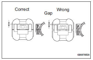
1. INSTALL NO. 1 COOLER THERMISTOR
(a) Install the No. 1 cooler thermistor as shown in the
illustration.
NOTICE:
Be sure to insert the thermistor only once
because reinserting it will no ...
 Blower unit
COMPONENTS
...
Other materials:
Touch screen gestures
Operations are performed by touching the screen directly with your
finger.
Operation method
Outline
Main use
Touch
Quickly touch and
release once.
Changing and selecting
various settings.
Drag*
Touch the screen
with your ...
Fold Seat Switch Circuit
DESCRIPTION
When the fold seat switch is operated, a switch operation signal is sent to
the fold seat control ECU. The
ECU receives switch operation signals from each switch and activates the folding
motor, reclining motor,
and release actuator.
WIRING DIAGRAM
INSPECTION PROCEDURE
1 IN ...
Disassembly
1. REMOVE STOP LIGHT SWITCH ASSEMBLY
(a) Turn the stop light switch assembly
counterclockwise and remove the stop light switch
assembly.
(b) Remove the stop light switch mounting adjuster
from the brake pedal support sub-assembly.
2. REMOVE STOP LIGHT SWITCH CUSHION
(a) Remove the stop ligh ...
