Toyota Sienna Service Manual: Installation
1. INSTALL COMPRESSOR AND MAGNETIC CLUTCH
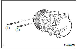
(a) Using a "TORX" socket wrench (E8), install the compressor and magnetic clutch with the 2 stud bolts.
Torque: 10 N*m (102 kgf*cm, 7.4 ft.*lbf)
HINT: Tighten the stud bolts in the order shown in the illustration.
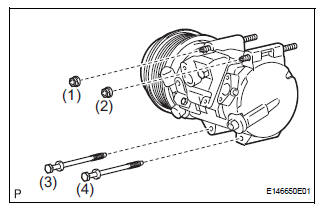
(b) Install the compressor and magnetic clutch with the 2 bolts and the 2 nuts.
Torque: 25 N*m (255 kgf*cm, 18 ft.*lbf)
HINT: Tighten the bolts and nuts in the order shown in the illustration.
(c) Connect the 2 clamps and wire harness.
(d) Connect the connector.
2. INSTALL SUCTION HOSE SUB-ASSEMBLY
(a) Remove the attached vinyl tape from the hose.
(b) Apply sufficient compressor oil to a new O-ring and the fitting surface of the compressor and magnetic clutch.
Compressor oil: ND-OIL 8 or equivalent
(c) Install the O-ring onto the suction hose subassembly.
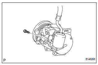
(d) Install the suction hose sub-assembly onto the compressor and magnetic clutch with the bolt.
Torque: 5.4 N*m (55 kgf*cm, 48 in.*lbf)
3. INSTALL DISCHARGE HOSE SUB-ASSEMBLY
(a) Remove the attached vinyl tape from the hose.
(b) Apply sufficient compressor oil to a new O-ring and the fitting surface of the compressor and magnetic clutch.
Compressor oil: ND-OIL 8 or equivalent
(c) Install the O-ring onto the discharge hose subassembly.
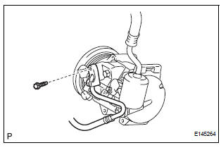
(d) Install the discharge hose sub-assembly onto the compressor and magnetic clutch with the bolt.
Torque: 5.4 N*m (55 kgf*cm, 48 in.*lbf)
4. INSTALL RADIATOR AND FAN ASSEMBLY
(See page CO-39)
5. INSTALL V-RIBBED BELT (See page EM-7)
6. INSTALL FRONT FENDER APRON SEAL RH (See page EM-62)
7. INSTALL FRONT WHEEL RH
8. CHARGE WITH REFRIGERANT (See page AC-173)
9. WARM UP ENGINE
10. INSPECT FOR REFRIGERANT LEAK (See page AC- 173)
 Reassembly
1. INSTALL MAGNETIC CLUTCH ASSEMBLY
(a) Install the magnetic clutch stator while aligning the
protrusion on the stator with the notch on the air
compressor assembly as shown in the illustration ...
 Condenser
COMPONENTS
...
Other materials:
System description
1. CRUISE CONTROL SYSTEM
This system is controlled by the ECM, and is activated by
the throttle position sensor and motor. The ECM controls
the following functions: ON-OFF, - (COAST)/SET, +
(ACCEL)/RES (RESUME), CANCEL, vehicle speed
operation, motor output control, and overdrive control.
& ...
Power Slide Door Warning Buzzer LH does not Sound
DESCRIPTION
The power slide door system uses warning buzzers built into LH
slide doors respectively. Each buzzer
has 2 ways of sounding that are used differently according to the
situations.
When all the following conditions are met, the warning buzzer sounds at
a cycle of ...
Inspection
1. Inspect generator clutch pulley
(a) Hold the center of the pulley, and confirm that the
outer ring turns counterclockwise and does not turn
clockwise.
If the result is not as specified, replace the clutch
pulley.
2. Remove generator drive end frame bearing
(a) Check that the bear ...
