Toyota Sienna Service Manual: Installation
1. INSTALL COOLER CONDENSER CORE
(a) Install the cooler condenser core with the 2 screws.
Torque: 3.9 N*m (40 kgf*cm, 35 in.*lbf)
HINT: If the condenser is replaced with a new one, add compressor oil to the new condenser.
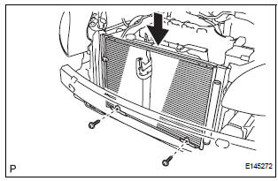
Capacity: 40 cc (1.4 fl.oz.) Compressor oil: ND-OIL 8 or equivalent
2. INSTALL NO. 1 RADIATOR SUPPORT (See page CO- 40)
3. INSTALL RADIATOR SUPPORT CUSHION (See page CO-41)
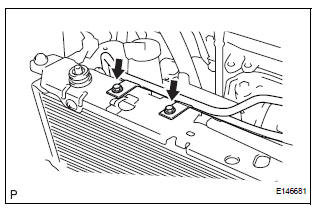
4. CONNECT NO. 2 OIL COOLER OUTLET TUBE SUBASSEMBLY
(a) Install the No. 2 oil cooler outlet tube sub-assembly with the 2 bolts.
Torque: 6.0 N*m (61 kgf*cm, 53 in.*lbf)
5. INSTALL UPPER RADIATOR SUPPORT SUBASSEMBLY (See page CO-42)
6. CONNECT COOLING FAN ECU (See page CO-42)
7. INSTALL HOOD LOCK SUPPORT SUB-ASSEMBLY (See page CO-43)
8. INSTALL HOOD LOCK ASSEMBLY (See page CO-43)
9. INSTALL HOOD LOCK RELEASE LEVER PROTECTOR (See page CO-44)
10. INSTALL NO. 1 AIR CLEANER INLET (See page EM- 59)
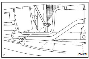
11. INSTALL COOLER REFRIGERANT LIQUID PIPE A
(a) Remove the attached vinyl tape from the pipe and the connecting part of the cooler condenser core.
(b) Sufficiently apply compressor oil to a new O-ring and the fitting surface of the pipe joint.
Compressor oil: ND-OIL 8 or equivalent
(c) Install the O-ring on the cooler refrigerant liquid pipe A.
(d) Install the cooler refrigerant liquid pipe A on the cooler condenser core with the bolt.
Torque: 5.4 N*m (55 kgf*cm, 47 in.*lbf)
12. INSTALL DISCHARGE HOSE SUB-ASSEMBLY
(a) Remove the attached vinyl tape from the tube and the connecting part of the cooler condenser core.
(b) Sufficiently apply compressor oil to a new O-ring and the fitting surface of the hose joint.
Compressor oil: ND-OIL 8 or equivalent
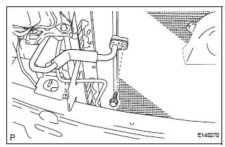
(c) Install the O-ring on the discharge hose subassembly.
(d) Install the discharge hose sub-assembly on the cooler condenser core with the bolt.
Torque: 5.4 N*m (55 kgf*cm, 47 in.*lbf)
13. INSTALL FRONT BUMPER ASSEMBLY (See page ET- 9)
14. INSTALL NO. 2 AIR CLEANER INLET (See page EM- 60)
15. CHARGE WITH REFRIGERANT (See page AC-173)
16. WARM UP ENGINE
17. INSPECT FOR REFRIGERANT LEAK (See page AC- 173)
18. VEHICLE PREPARATION FOR FOG LIGHT AIMING (w/ Fog Light) (See page LI-82)
19. PREPARATION FOR FOG LIGHT AIMING (w/ Fog Light) (See page LI-83)
20. FOG LIGHT AIMING INSPECTION (w/ Fog Light) (See page LI-84)
21. FOG LIGHT AIMING ADJUSTMENT (w/ Fog Light) (See page LI-85)
 Reassembly
1. INSTALL COOLER DRYER
(a) Using needle nose pliers, install the cooler dryer.
(b) Install a new O-ring on the cap.
(c) Sufficiently apply compressor oil to the fitting
surfaces of the ...
 Room temperature sensor
On-vehicle inspection
1. INSPECT A/C ROOM TEMPERATURE SENSOR
(a) Remove the A/C room temperature sensor.
(b) Measure the resistance according to the value(s) in
the table below.
Standard re ...
Other materials:
On-vehicle inspection
1. INSPECT STEERING PAD (VEHICLE NOT INVOLVED IN COLLISION)
Perform a diagnostic system check.
With the steering pad installed on the vehicle,
perform a visual check. If there are any defects as
mentioned below, replace the steering pad with a
new one:
Cuts, minute cracks or ...
Adjustment
1. VEHICLE PREPARATION FOR HEADLIGHT AIMING
ADJUSTMENT
Prepare the vehicle:
Ensure there is no damage or deformation to the
body around the headlights.
Fill the fuel tank.
Make sure that the oil is filled to the specified
level.
Make sure that the c ...
Hood
COMPONENTS
Adjustment
HINT:
Since a centering bolt is used as a hood hinge mounting bolt
and hood lock mounting bolt, the hood and hood lock can not
be adjusted with them on. Substitute a bolt with a washer for
the centering bolt.
1. INSPECT HOOD SUB-ASSEMBLY
Check that the clearance is ...
