Toyota Sienna Service Manual: Installation
1. INSTALL 3 POINT TYPE NO. 2 REAR SEAT BELT ASSEMBLY
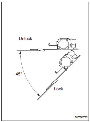
- Check the degree of tilt when the belt begins to lock the ELR.
- Check that the belt does not lock within 15 of
tilt in all directions but that the belt locks with
over 45 of tilt, when gently moving the
retractor.
If operation is not as specified, replace the 3 point type No. 2 rear seat belt assembly.
- Install the 3 point type No. 2 rear seat belt assembly
with the 3 bolts and 2 nuts.
Torque: 42 N*m (430 kgf*cm, 31 ft.*lbf)
- Check the ELR lock.
NOTICE: The check should be performed with the assembly installed.
- Check that the belt locks when pulling out the
belt quickly when the belt is installed.
If operation is not as specified, replace the 3 point type No. 2 rear seat belt assembly.
- Check the fastening function of the child restraint system.
NOTICE: The check should be performed with the assembly installed.
- Check that the belt cannot be pulled out any more but can be rewound after the belt is fully pulled out.
- Check that the belt can be pulled out and
rewound after the belt is fully rewound.
If operation is not as specified, replace the 3 point type No. 2 rear seat belt assembly.
- Install the roof headlining.
HINT: Refer to the instructions for installation of the roof headlining.
2. INSTALL NO. 1 REAR SEAT OUTER BELT ASSEMBLY (for 8-Passenger)
HINT: Refer to the instructions for reassembly of the rear No .1 seat assembly (for center seat).
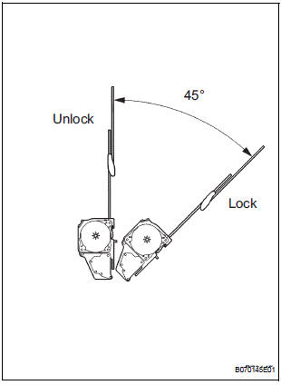
- Check the degree of tilt when the belt begins to lock the ELR.
- Check that the belt does not lock within 15 of
tilt in all directions but that the belt locks with
over 45 of tilt, when gently moving the
retractor.
If operation is not as specified, replace the No.
1 rear seat outer belt assembly.
- Install the No. 1 rear seat outer belt assembly with
the 2 bolts and 2 nuts.
Torque: 42 N*m (430 kgf*cm, 31 ft.*lbf)
- Check the ELR lock.
NOTICE: The check should be performed with the assembly installed.
- Check that the belt locks when pulling out the belt quickly when the belt is installed.
HINT: The seat belt does not lock when the pull out amount of the belt is 955 mm (37.60 in.) or less.
If operation is not as specified, replace the No.
1 rear seat outer belt assembly.
- Check the fastening function of the child restraint system.
NOTICE: The check should be performed with the assembly installed.
- Check that the belt cannot be pulled out any more but can be rewound after it is fully pulled out.
- Check that the belt can be pulled out and
rewound after the belt is fully rewound.
If operation is not as specified, replace the No.
1 rear seat outer belt assembly.
- Install the rear seat shoulder belt cover.
- Install the rear seatback board.
 Removal
1. REMOVE NO. 1 REAR SEAT OUTER BELT
ASSEMBLY (for 8-Passenger)
HINT:
Refer to the instructions for disassembly of the rear No .1 seat assembly (for
center seat).
Remove the rear seatba ...
 Theft deterrent
...
Other materials:
For manual air conditioning system
ON-VEHICLE INSPECTION
1. INSPECT AIR INLET CONTROL SERVO MOTOR
(a) Remove the air inlet control servo motor.
(b) Connect the positive (+) lead from the battery to
terminal 5 and negative (-) lead to terminal 1, then
check that the lever turns to "RECIRCULATION"
side smoothly.
...
Open in Stop Light Switch Circuit
DTC C1249/49 Open in Stop Light Switch Circuit
DESCRIPTION
This skid control ECU inputs the stop light switch signal and detects the
status of brake operation.
The skid control ECU has an open detection circuit. If an open in the stop light
switch input line or GND
side stop light circuit ...
Removal
1. DISCONNECT CABLE FROM NEGATIVE BATTERY
TERMINAL
2. REMOVE FRONT DOOR SCUFF PLATE LH
3. REMOVE COWL SIDE TRIM SUB-ASSEMBLY LH
4. REMOVE LOWER INSTRUMENT PANEL FINISH
PANEL SUB-ASSEMBLY LH (See page IP-6)
5. REMOVE TIRE PRESSURE WARNING RESET SWITCH
(a) Disengage the 2 claws and remove t ...
