Toyota Sienna Service Manual: Installation
1. INSTALL ACCESSORY METER ASSEMBLY

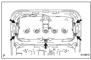
- Using torx socket wrench (T10), install the accessory meter assembly with the 5 screws.
2. INSTALL ROOF CONSOLE BOX ASSEMBLY
 Removal
1. REMOVE ROOF CONSOLE BOX ASSEMBLY
2. REMOVE ACCESSORY METER ASSEMBLY
Using torx socket wrench (T10), remove the 5
screws and accessory meter assembly.
...
 Fuel sender gauge
assembly
INSPECTION
1. INSPECT FUEL SENDER GAUGE ASSEMBLY
Disconnect the connector from the fuel sender
gauge.
Check that the float moves smoothly between F and
E.
Measure th ...
Other materials:
CD Sound Skips
INSPECTION PROCEDURE
1 CHECK CD
Check the CD.
OK:
The CD is clean.
HINT:
If dirt is on the CD surface, wipe it clean with a soft cloth
from the inside to the outside in a radial direction.
NOTICE:
Do not use a conventional record cleaner or antistatic
preservative.
2 CHECK CD
...
Removal
1. REMOVE INSTRUMENT CLUSTER CENTER NO. 1 FINISH PANEL
2. REMOVE INSTRUMENT CLUSTER CENTER NO. 2
FINISH PANEL
3. REMOVE SHIFT LEVER KNOB SUB-ASSEMBLY
4. REMOVE POSITION INDICATOR HOUSING ASSEMBLY
5. REMOVE INSTRUMENT CLUSTER CENTER LOWER FINISH PANEL SUB-ASSEMBLY
6. REMOVE POWER POINT SOCKET A ...
DVD-ROM Abnormal
DVD-ROM Abnormal
DESCRIPTION
DTC No.
DTC Detection Condition
Trouble Area
44-43
DVD-ROM operation is abnormal.
DVD
Television display assembly
INSPECTION PROCEDURE
HINT:
After the inspection is completed, clear the DTCs ...
